Vehicle Front Structure

a front structure and vehicle technology, applied in the direction of roofs, vehicle sub-unit features, jet propulsion mounting, etc., can solve the problems of ineffective receiving collision load and ineffective transmission of collision load to the rear side of the vehicl

Inactive Publication Date: 2007-11-15
TOYOTA JIDOSHA KK
View PDF33 Cites 10 Cited by
  • Summary
  • Abstract
  • Description
  • Claims
  • Application Information

AI Technical Summary

Benefits of technology

[0006] An embodiment of the invention seeks to provide a vehicle front structure in which a cross member above paired side members can effectively receive a collision load.

Problems solved by technology

Thus, there is a possibility that the collision input member cannot effectively receive the collision load, and cannot efficiently transmit the collision load to a rear side of the vehicle.

Method used


Image

  • Vehicle Front Structure
  • Vehicle Front Structure
  • Vehicle Front Structure

Examples


first embodiment

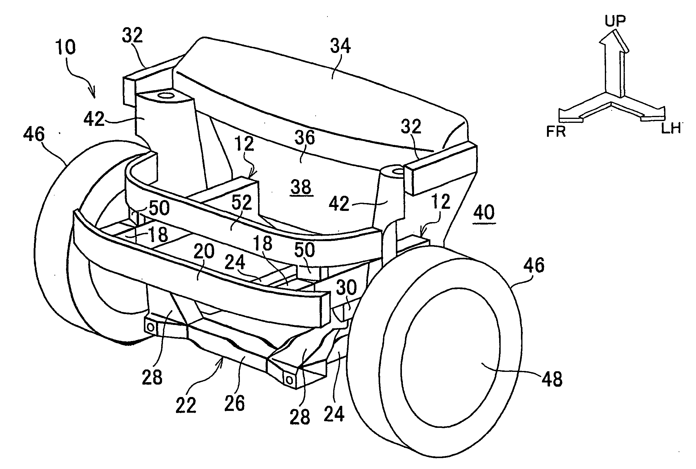
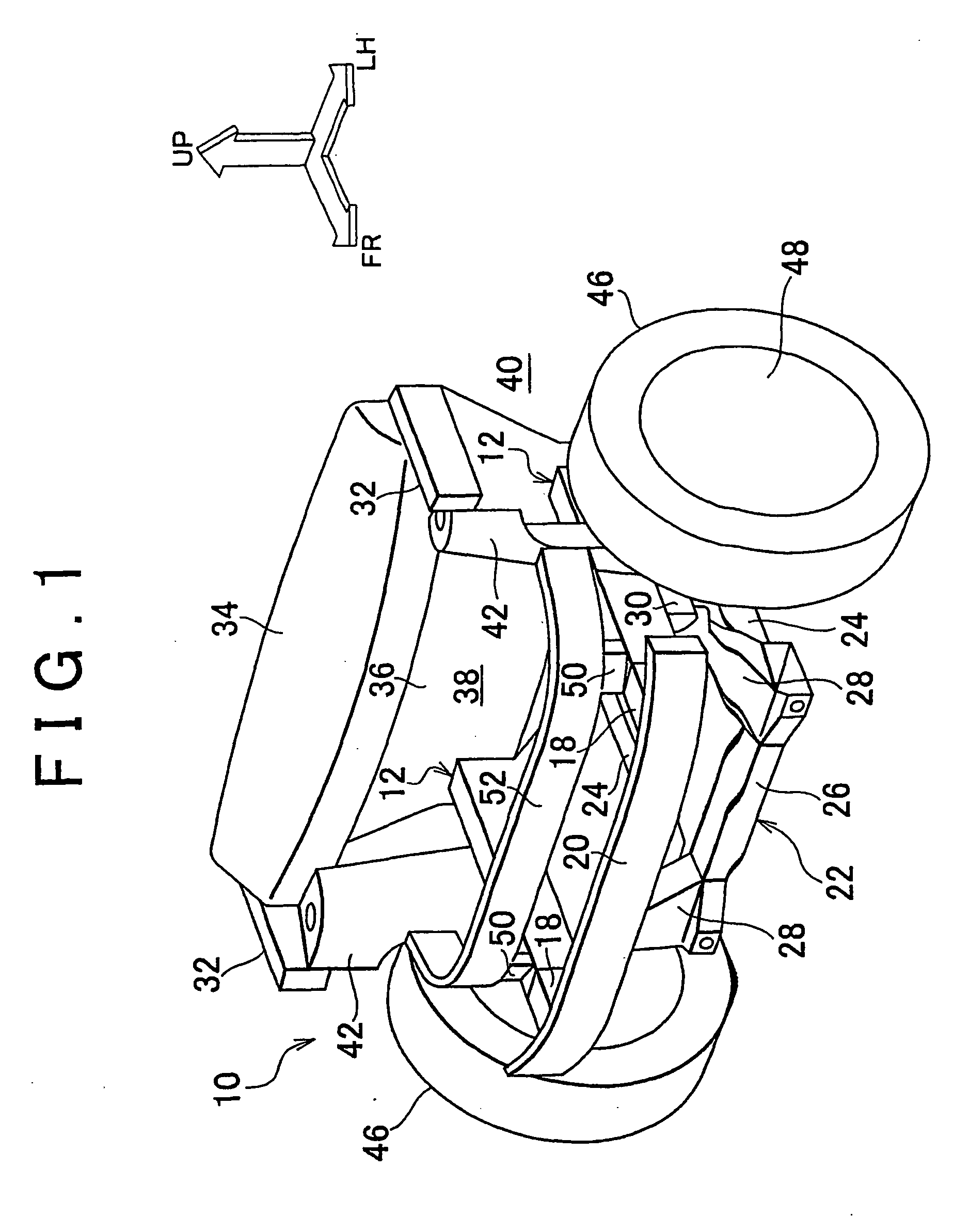
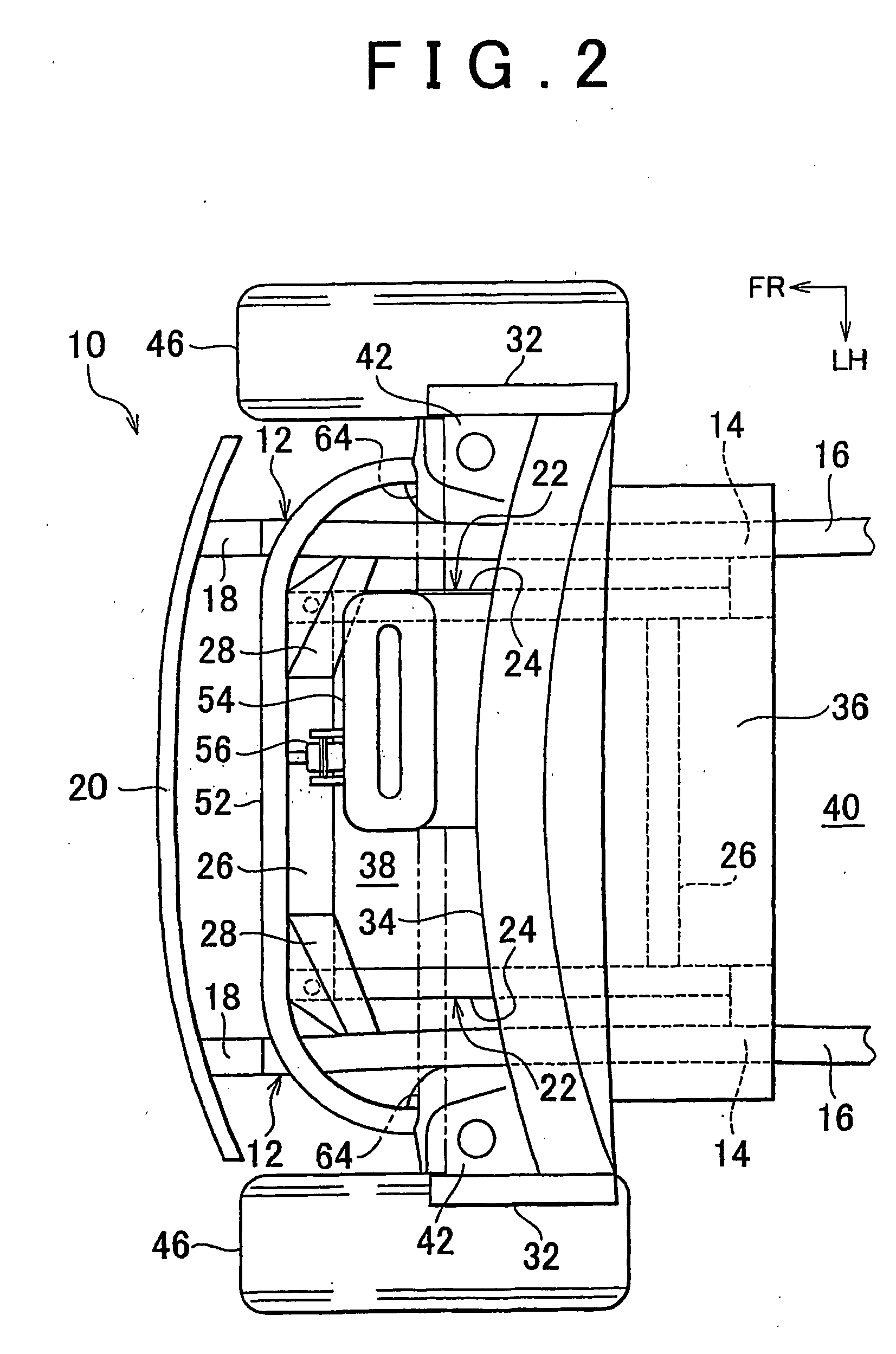
[0043]FIG. 1 is a schematic perspective view showing a vehicle front structure 10 according to a first embodiment of the invention when diagonally seen from a position ahead of, and on a left side of a vehicle. Further, FIG. 2 is a plan view showing the vehicle front structure 10 according to the first embodiment of the invention when seen from above the vehicle. FIG. 3 is a lateral view showing the vehicle front structure 10 according to the first embodiment of the invention when seen from a position on the left side of the vehicle. In figures, an arrow FR indicates a position ahead of the vehicle, an arrow LH indicates a position on the left side of the vehicle, and an arrow UP indicates a position above the vehicle.

[0044] The vehicle front structure 10 according to the embodiment includes paired front side members 12 having a long rectangular tube shape, which serve as side members. The paired front side members 12 are disposed along a vehicle longitudinal direction at a right s...

second embodiment

[0073]FIG. 5 is a schematic perspective view showing a vehicle front structure 70 according to a second embodiment of the invention when diagonally seen from a position ahead of, and on the left side of the vehicle.

[0074] The vehicle front structure 70 according to the second embodiment of the invention has substantially the same configuration as that of the vehicle front structure 10 according to the first embodiment. However, the vehicle front structure 70 is different from the vehicle front structure 10 in the following points.

[0075] In the vehicle front structure 70 according to the second embodiment, the cross member 52 is made of highly air-tight material such as an extrusion material. Intake air ports 72 are provided at both ends of the cross member 52. Each of the intake air ports 72 is opened into an inside of the corresponding suspension tower 42.

[0076] The power unit 54 (not shown in FIG. 5) and the cross member 52 are not connected with each other using the torque rod...

third embodiment

[0081]FIG. 7 is a schematic perspective view showing a vehicle front structure 80 according to a third embodiment of the invention when diagonally seen from a position ahead of, and on a left side of a vehicle.

[0082] The vehicle front structure 80 according to the third embodiment has substantially the same configuration as that in the first embodiment. However, the vehicle front structure 80 according to the third embodiment is different from the vehicle front structure 10 according to the first embodiment in the following points.

[0083] In the vehicle front structure 80 according to the third embodiment, the paired braces 50 that are provided in the first embodiment are not provided. The cross member 52 is not connected with the paired front side members 12, and is disposed above the paired front side members 12 so as to be separated from the paired front side members 12.

[0084] In the third embodiment as well, it is possible to obtain the same actions and effects as those obtain...


PUM


Abstract

In a vehicle front structure (10), a cross member (52) which is disposed above paired side members (12) includes vehicle width-direction both end portions extending toward a rear side of the vehicle. The cross member (52) is connected with vehicle front-side portions of the paired suspension towers (42) at edges of the extending portions. Therefore, when a vehicle has a frontal collision at high speed, a collision load applied to the cross member (52) can be effectively received by the paired suspension towers (42), and can be transmitted to the paired suspensions. Thus, the cross member (52) can effectively receive the collision load, and can efficiently transmit the collision load to the rear side of the vehicle.

Description

BACKGROUND OF THE INVENTION [0001] 1. Field of the Invention [0002] The invention relates to a vehicle front structure in which a cross member is provided above paired side members. [0003] 2. Description of the Related Art [0004] A vehicle front structure is disclosed, in which one of paired brackets is fixed to one of paired side rails, and the other of the paired brackets is fixed to the other of the paired side rails, and a collision input member is fixed between the paired brackets via a pipe member. For example, Japanese Patent Application Publication No. JP-A-7-69241 discloses such a vehicle front structure. [0005] However, in this vehicle front structure, the shock input member and the pipe member are simply supported by an upper surface of the side rails via the brackets. Therefore, when a vehicle has a frontal collision, a large collision load is input particularly to lower ends of the brackets from the collision input member. Thus, there is a possibility that the collision...

Claims


Application Information

Patent Timeline
Patent Type & Authority Applications(United States)
IPC IPC(8): B62D25/08
CPCB62D21/152B62D25/085B62D25/088B60Y2306/01
Inventor ASAI, TAKASHI
Owner TOYOTA JIDOSHA KK
Why Eureka
Try Eureka