Front vehicle-body structure of vehicle

a front vehicle and body technology, applied in the direction of roofs, vehicle arrangements, transportation and packaging, etc., can solve the problems of insufficient rigidity of the joint portion of the cow panel, and insufficient rigidity of the brace and the cowl member for this vertical displacement restraint. achieve the effect of improving the rigidity of the vehicle body

Active Publication Date: 2016-02-04
MAZDA MOTOR CORP
View PDF26 Cites 6 Cited by
  • Summary
  • Abstract
  • Description
  • Claims
  • Application Information

AI Technical Summary

Benefits of technology

[0007]Accordingly, an object of the present invention is to provide a front vehicle-body structure of a vehicle which can properly restrain the vertical displacement of the top of the suspension tower, thereby improving the vehicle-body rigidity.

Problems solved by technology

Herein, there is a problem in that since a top of the suspension tower supports a damper device of a front suspension, an inclination angle of the suspension tower may be changed by a load which is generated in a vertical direction (i.e., a vertical load) during a vehicle traveling and this change of the suspension tower's inclination angle may have an influence on the maneuverability and stability of the vehicle.
However, there is a concern that while this front vehicle-body structure can restrain a longitudinal displacement of the top of the suspension tower, a vertical displacement of the top of the suspension tower may not be restrained sufficiently by this front vehicle-body structure as specifically described below.
First, since the upper face of the top of the suspension tower is pressed down by the connecting bracket joined to the upper face of the top plate of the cowl box and the upper wall of the wheel apron in this front vehicle-body structure, only a joint force of the brace to the top plate of the cowl box contributes to restraint of the vertical displacement of the top of the suspension tower, so that the rigidity of both the brace and the cowl member may not be utilized sufficiently for this vertical-displacement restraint.
Secondly, since a joint portion to join the connecting bracket to the cowl panel needs to be provided newly in a case in which the open cowl structure is applied, there is a concern that the support rigidity of the joint portion for the cow panel may become insufficient.

Method used


Image

  • Front vehicle-body structure of vehicle
  • Front vehicle-body structure of vehicle
  • Front vehicle-body structure of vehicle

Examples


Embodiment Construction

[0023]Hereafter, an embodiment of the present invention will be described specifically referring to the drawings. The following description exemplifies the present invention which is applied to a vehicle, but the present invention should not be limited to this.

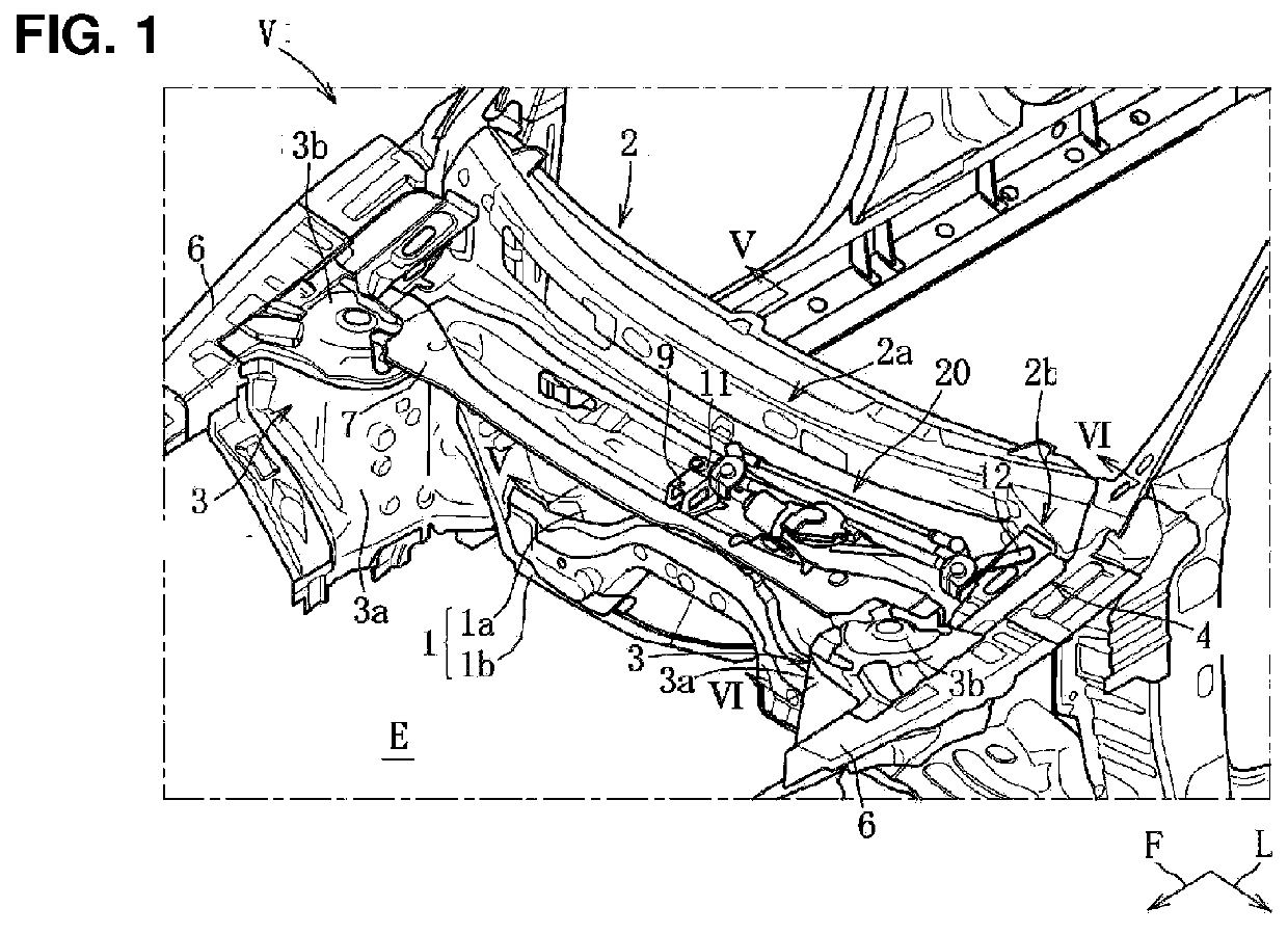
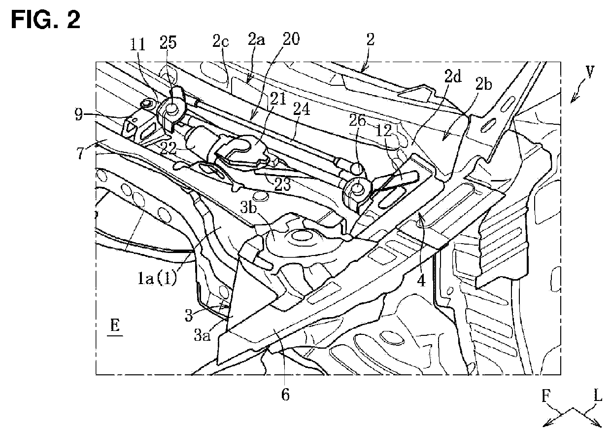
[0024]Hereafter, the embodiment of the present invention will be described referring to FIGS. 1-6. As shown in FIGS. 1 and 2, a vehicle V comprises a dash panel 1 which partitions an engine room E from a vehicle compartment, a cowl panel 2 which is provided above the dash panel 1 and extends in a vehicle width direction, a pair of right-and-left suspension towers 3 which are provided to protrude toward the inside of the engine room E, and a pair of right-and-left connecting brackets 4 which connect the pair of suspension towers 3 and the cowl panel 2, respectively. Herein, an arrow F shows a forward direction, and an arrow L shows a leftward direction.

[0025]The dash panel 1 comprises a vertical wall portion la which extends ve...


PUM


Abstract

There are provided a cowl panel provided above a dash panel partitioning an engine room from a vehicle compartment and extending in a vehicle width direction, a suspension tower protruding toward an inside of the engine room and supporting a front suspension, and a connecting bracket connecting the suspension tower and the cowl panel and configured to slant rearward and upward, wherein the connecting bracket comprises a front-end flange portion and a rear-end flange portion, the front-end flange portion is joined to a slant portion formed at a rear portion of a top of the suspension tower which is configured to slant rearward and downward, and the rear-end flange portion is configured to rise upward via a bending portion and joined to a vertical wall portion of the cowl panel.

Description

BACKGROUND OF THE INVENTION[0001]The present invention relates to a front vehicle-body structure of a vehicle, and in particular, relates to the front vehicle-body structure of the vehicle which comprises a connecting bracket connecting a cowl panel and a suspension tower.[0002]Conventionally, a front vehicle-body structure of a vehicle comprising a cowl panel provided above a dash panel which partitions an engine room from a vehicle compartment and extends in a vehicle width direction and a suspension tower protruding toward an inside of the engine room and supporting a front suspension is known. Herein, there is a problem in that since a top of the suspension tower supports a damper device of a front suspension, an inclination angle of the suspension tower may be changed by a load which is generated in a vertical direction (i.e., a vertical load) during a vehicle traveling and this change of the suspension tower's inclination angle may have an influence on the maneuverability and ...

Claims


Application Information

Patent Timeline
Patent Type & Authority Applications(United States)
IPC IPC(8): B62D25/08B62D25/14
CPCB62D25/088B62D25/145B62D25/085B62D25/081B62D25/082
Inventor NAKAUCHI, SHIGERUNAKAYAMA, NOBUYUKIKANEMORI, MASAHIDE
Owner MAZDA MOTOR CORP
Why Eureka
Try Eureka