Passenger vehicle front floor framework structure

A skeleton structure and front floor technology, which is applied to the superstructure, superstructure sub-assemblies, vehicle components, etc., can solve the problems of insufficient living space for occupants, increased rearward movement of installation points, and vulnerable thighs, etc. The effect of structural deformation, reduction of deformation, and improvement of frontal collision performance

Active Publication Date: 2014-01-22
DONGFENG MOTOR CORP HUBEI
View PDF5 Cites 10 Cited by
  • Summary
  • Abstract
  • Description
  • Claims
  • Application Information

AI Technical Summary

Problems solved by technology

At present, since the installation point of the front bracket is on the front side beam and the side beam connecting plate of the vehicle body, the deformation of the front side beam during the frontal collision drives the deformation of the side beam connecting plate and the inner side beam of the front floor through the front bracket, resulting in During the fron

Method used


Image

  • Passenger vehicle front floor framework structure
  • Passenger vehicle front floor framework structure
  • Passenger vehicle front floor framework structure

Examples


Embodiment Construction

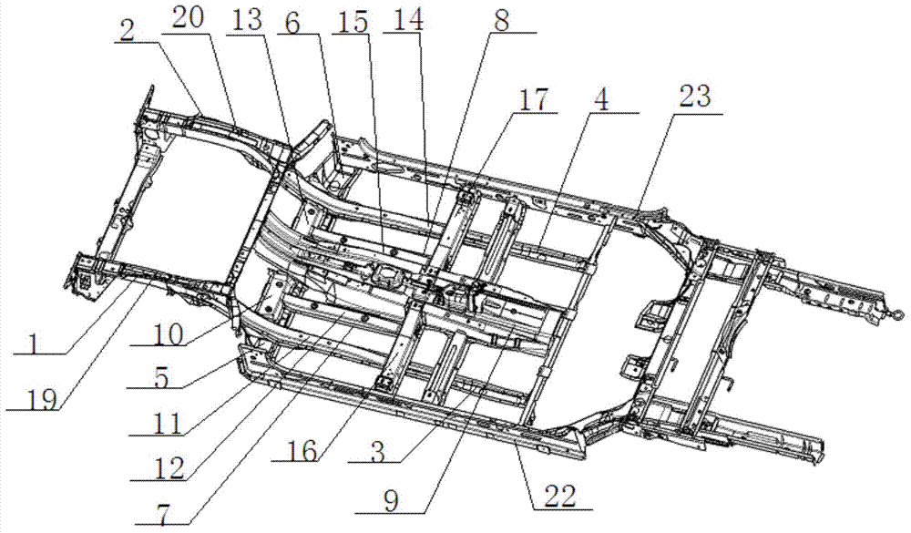
[0022] The present invention will be further described in detail below in conjunction with the accompanying drawings to facilitate a clearer understanding of the present invention, but they do not limit the present invention.

[0023] Such as figure 1 As shown, a front floor skeleton structure of a passenger car includes a left front side beam 1 and a right front side beam 2 under the front floor, and a left front side beam cover plate 19 is arranged on the left front side beam 1 , and the right front side beam 2 There is a right front longitudinal beam cover plate 20 on the top, the rear end of the left front longitudinal beam 1 is connected to the front floor left inner longitudinal beam 3, the rear end of the right front longitudinal beam 2 is connected to the front floor right inner longitudinal beam 4, and the left front longitudinal beam A dash panel beam 21 is connected between the rear end of the beam 1 and the rear end of the right front longitudinal beam 2, and a tra...


PUM


Abstract

The invention discloses a passenger vehicle front floor framework structure. A left longitudinal beam connection plate cover plate is arranged above a front floor and corresponds to a left longitudinal beam connection plate, the left end of the left longitudinal beam connection plate cover plate is connected with a front floor left inner longitudinal beam cover plate corresponding to a left inner longitudinal beam, and the middle of the left longitudinal beam connection plate cover plate is connected with a second left inner longitudinal beam cover plate corresponding to a second left inner longitudinal beam. A right longitudinal beam connection plate cover plate is arranged above the front floor and corresponds to a right longitudinal beam connection plate, the right end of the right longitudinal beam connection plate cover plate is connected with a front floor right inner longitudinal beam cover plate corresponding to a right inner longitudinal beam, and the middle of the right longitudinal beam connection plate cover plate is connected with a second right inner longitudinal beam cover plate corresponding to a second right inner longitudinal beam. Reinforcing parts are ingeniously added above the floor, the longitudinal rigidity of a front floor framework beam and the strength of a front bracket rear installation point are improved, the deformation amount of the inner longitudinal beams in the collision process and the backward movement amount of the front bracket rear installation point are decreased, a living space of passengers is further enlarged, and the head-on collision performance of a passenger vehicle is improved.

Description

technical field [0001] The invention relates to the vehicle body floor technology of a passenger car, in particular to a front floor frame structure of a passenger car. Background technique [0002] Safety is an important concern in the process of automobile research and development. Ensuring the safety of occupants during collisions is the consistent pursuit of the automobile industry. Among them, improving the collision performance of the front floor structure is one of the important means to improve automobile safety. At present, since the installation point of the front bracket is on the front side beam and the side beam connecting plate of the vehicle body, the deformation of the front side beam during the frontal collision drives the deformation of the side beam connecting plate and the inner side beam of the front floor through the front bracket, resulting in During the frontal collision, the deformation of the inner longitudinal beam of the floor and the rearward mov...

Claims


Application Information

Patent Timeline
IPC IPC(8): B62D25/20
Inventor 李仲奎李峥秦信武屈新田阳奕鹏
Owner DONGFENG MOTOR CORP HUBEI
Why Eureka
Try Eureka