
Bolt with a handle

Inactive Publication Date: 2005-01-06
RAMSAUER DIETER
View PDF38 Cites 17 Cited by
  • Summary
  • Abstract
  • Description
  • Claims
  • Application Information

AI Technical Summary

Benefits of technology

[0010] This step does away with axial displacement of the locking rod, so that complicated transmission devices for transforming the movement of a hand lever, either a rotational movement or swiveling movement or some other movement, into an axial displacement of the locking rod can be eliminated. Further, locking elements need no longer be arranged or formed on the rod, so that manufacture of the locking rod is limited to sawing off a piece of the profile rod to an appropriate length corresponding to the cabinet height. In some cases, the ends of the rod are to be rounded off so as to improve pivoting bearing support.
[0011] However, a bearing support of the locking rod, particularly when it is a flat strip rod, can also be carried out in a very simple manner in that the profiled rod is received in a partially circular or triangular receiving space of a rod guide element.
[0014] The rod guide element can comprise a spring device which pushes the rod into the locked position. The closure rod accordingly forms a kind of latch which makes it possible to push the door leaf against the door frame and accordingly lock the closure without actuating the closure.
[0015] The actuating arrangement can comprise an actuating device, e.g., a lever, which is supported around an axis parallel to the door leaf plane and which swivels into the open position against the force of the spring, or a spring, when the profiled rod is actuated. An actuating lever of this kind can be lockable, e.g., outfitted or not outfitted with a lock. A particularly simple design results when the actuating arrangement comprises a lever which reaches through an opening in the door leaf and which is rigidly connected, e.g., clamped, to the profiled rod. This eliminates the need for a special bearing support of the hand lever on the door leaf because this bearing support is taken over by the profiled locking rod. An additional handle for actuating the door may be provided in addition to this actuating lever.
[0017] Also, for a simple construction the holding element arranged at the door frame is constructed as a steel angle. In particular, it is possible in this way to combine a rod closure of the type according to the invention with hinge devices requiring bore holes, openings or threaded bore holes in the frame which are also available in an analogous manner for fastening the steel angle. This has the advantage that the door leaf can be turned around without changing the hole configuration in the frame, so that a door hung on the left-hand side can be converted to a right-handed door.
[0019] Further, in order to reduce noise and lessen the leverage required for the process of swiveling the door, the rod guide element is advantageously made of plastic.

Problems solved by technology

Further, locking elements need no longer be arranged or formed on the rod, so that manufacture of the locking rod is limited to sawing off a piece of the profile rod to an appropriate length corresponding to the cabinet height.

Method used


Image

  • Bolt with a handle
  • Bolt with a handle
  • Bolt with a handle

Examples


Embodiment Construction

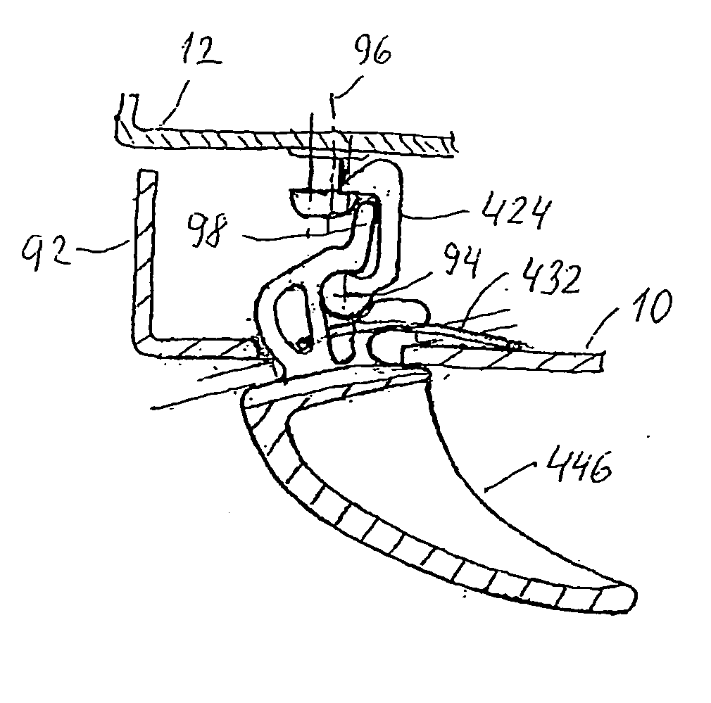
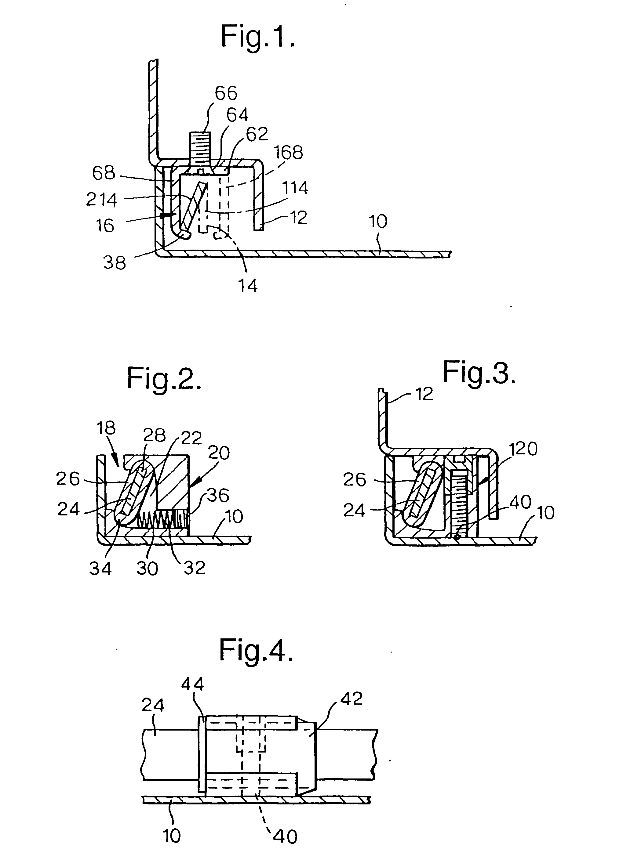
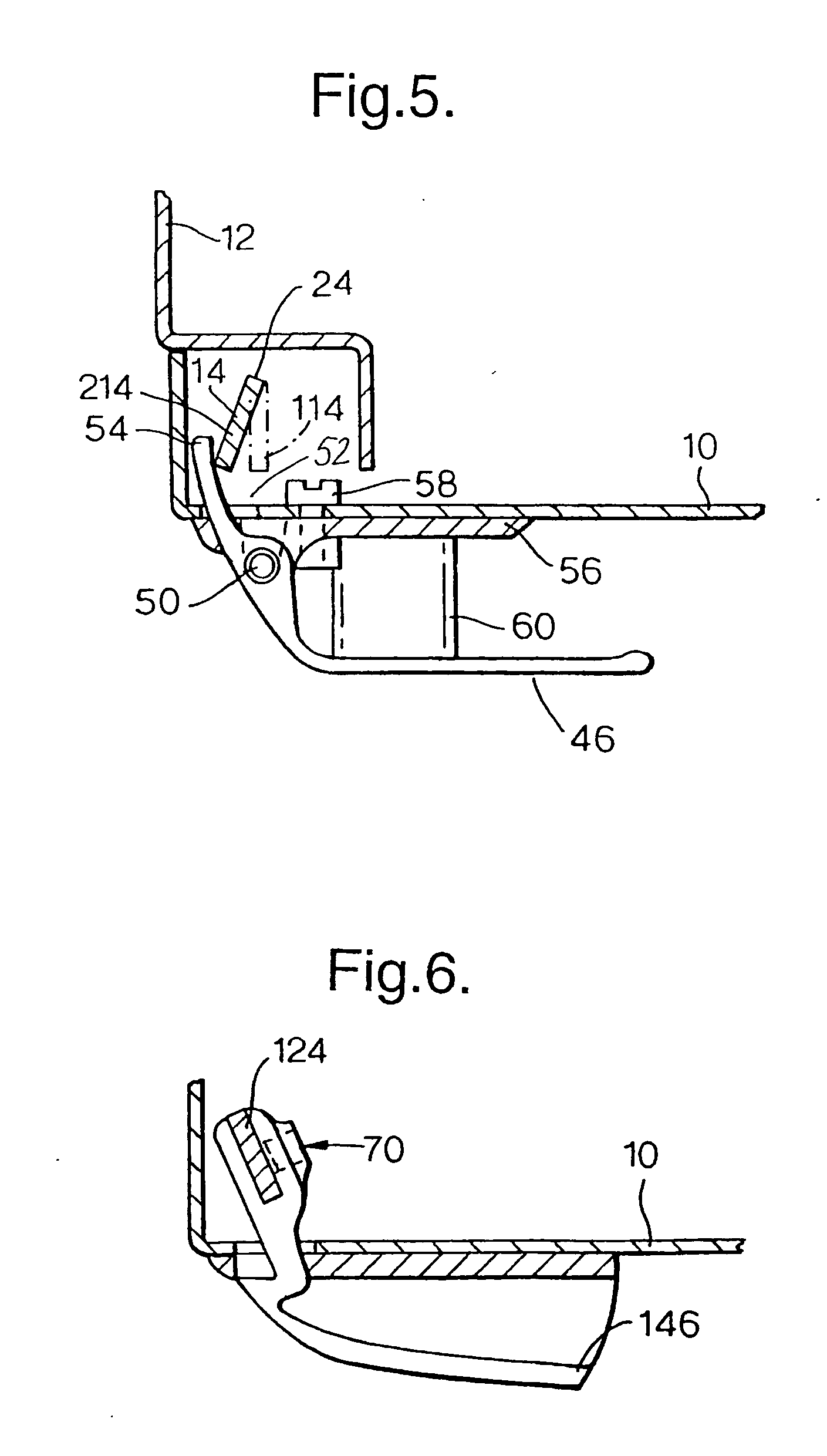
[0050]FIG. 1 shows a cross-sectional view of a sheet-metal cabinet door 10 which is articulated at a door frame 12 in a manner not shown in more detail. Alternatively, this may be a flap 10 which locks an opening formed by the frame 12. A flat strip rod 14 which is arranged parallel to the door edge or flap edge substantially edgewise to the door plane or flap plane is used for locking the door or flap in the closed state. According to the view shown by solid lines in FIG. 1, this flat strip rod 14 engages a holding element 16 arranged at a door frame 12 and accordingly prevents the door from being opened.

[0051] The flat strip rod 14 can be swiveled (rotated) out of this closed position shown in solid lines in FIG. 1 into an open position shown in dashed lines, in which position it releases the holding element 16 so that it is possible for the door to be swung out.

[0052] To enable these two positions of the flat strip rod shown in FIG. 1, that is, the closed position and open posi...


PUM


Abstract

The description relates to a rod closure for locking sheet-metal cabinet doors or the like doors or flaps, comprising a rod, such as a flat strip rod, which is profiled in an elongated manner, extends substantially edgewise parallel to the door edge and is preferably arranged in the bevel space, and at least one holding element which is arranged at the door frame for holding the rod so as to lock the door in the closed position, and an actuating device for the rod, which actuating device is connected to the door leaf. According to the invention, the rod or a complicated profiled rod is mounted so as to be swivelable between a locked position and an unlocked position around a longitudinal axis arranged close to the side directed away from the door leaf plane, and the holding element forms a contact surface for the other side of the rod facing the door leaf plane, and the actuation device engages the rod close to this side.

Description

CROSS-REFERENCE TO RELATED APPLICATIONS [0001] This application claims priority of International Application No. PCT / EP02 / 05772, filed May 25, 2002 and German Application No. 201 08 954.8, filed May 29, 2001, the complete disclosures of which are hereby incorporated by reference.BACKGROUND OF THE INVENION [0002] a) Field of the Invention [0003] The invention is directed to a rod closure for locking sheet-metal cabinet doors or the like doors or flaps in sheet-metal cabinet frames or the like door frames or housing frames, comprising a rod, such as a flat strip rod, which is profiled in an elongated manner, extends substantially edgewise parallel to the door edge at the door or at the frame and is preferably arranged in the bevel space, and at least one holding element which is arranged at the door frame or at the door for holding the profiled rod so as to lock the door in the closed position, and an actuating device for the profiled rod, which actuating device is connected to the do...

Claims


Application Information

Patent Timeline
IPC IPC(8): E05B15/04E05C3/16E05C9/08E05C9/18
CPCE05B2015/0431E05C3/162Y10S292/11E05C9/1875Y10S292/68E05C9/08Y10T292/0928Y10T292/0949Y10T292/108Y10T292/444Y10T292/57
Inventor RAMSAUER, DIETER
Owner RAMSAUER DIETER
Features
  • Generate Ideas
  • Intellectual Property
  • Life Sciences
  • Materials
  • Tech Scout
  • Unparalleled Data Quality
  • Higher Quality Content
  • 60% Fewer Hallucinations
Learn More