Method of charging and discharging a plurality of batteries

a battery and battery technology, applied in the direction of several simultaneous battery arrangements, secondary cell servicing/maintenance, transportation and packaging, etc., can solve the problems of battery performance drop, battery temperature can become abnormally high, and the charge and discharging takes time to fully charge all batteries, etc., to achieve the effect of low capacity of the battery supplying power to the electrical equipmen

Inactive Publication Date: 2005-01-06
SANYO ELECTRIC CO LTD
View PDF4 Cites 69 Cited by
  • Summary
  • Abstract
  • Description
  • Claims
  • Application Information

AI Technical Summary

Benefits of technology

The patent describes a method to prevent a battery from becoming too low and becoming unable to power electrical equipment. This is done by using another battery that has more capacity than the low battery. When the low battery reaches its minimum capacity, power is supplied from the other battery to charge it up. This way, the electrical equipment is always powered even if one battery becomes low.

Problems solved by technology

The patent text describes a method for using multiple batteries to power electrical equipment. The technical problem addressed in the text is how to efficiently switch between and charge multiple batteries without requiring a high capacity battery charger and making the battery charger large and expensive.

Method used


Image

  • Method of charging and discharging a plurality of batteries
  • Method of charging and discharging a plurality of batteries
  • Method of charging and discharging a plurality of batteries

Examples


Embodiment Construction

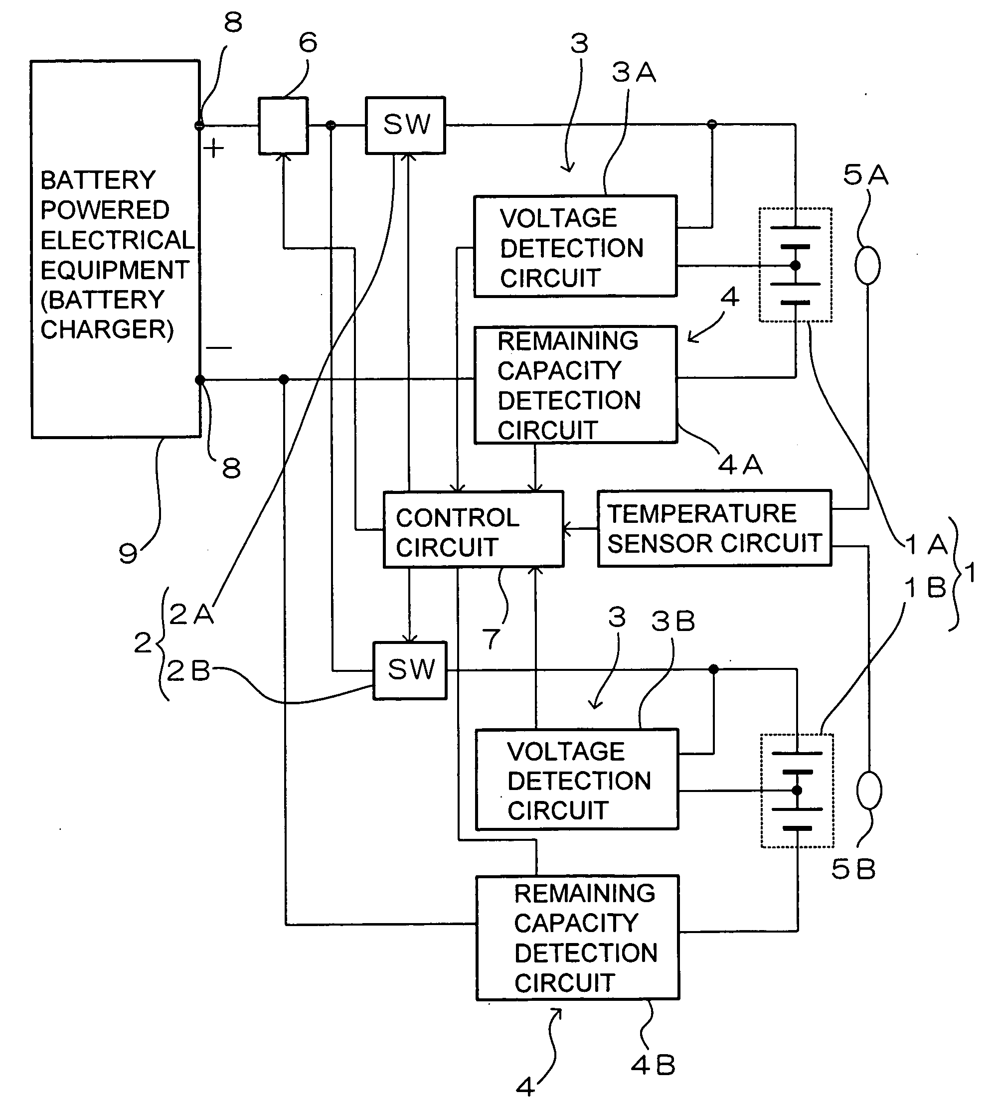
[0026]FIG. 1 shows a power supply circuit which switches to, and charges as well as discharges a first battery 1A and a second battery 1B, which are a plurality of batteries 1. This power supply circuit is provided with a constant current, voltage limited charging circuit 6 which charges batteries 1 by constant current charging or voltage limited charging, a first battery 1A and a second battery 1B, a first switch 2A and a second switch 2B connecting each battery 1 to an output terminal 8, a first voltage detection circuit 3A and a second voltage detection circuit 3B which detect the voltage of each battery 1, a first remaining capacity detection circuit 4A and a second remaining capacity detection circuit 4B which compute the remaining capacity of each battery 1, a first temperature sensor 5A and a second temperature sensor 5B which detect the temperature of each battery 1, and a control circuit 7 which controls the constant current, voltage limited charging circuit 6, switches the...


PUM


Abstract

The method of charging a plurality of batteries successively switches to, and charges a plurality of batteries one at a time. Batteries are charged by constant current until battery voltage reaches a prescribed voltage, or battery capacity reaches a prescribed capacity. After that, voltage limited charging is performed while regulating battery voltage. In the method of discharging a plurality of batteries, the discharging battery is discharged until remaining capacity drops below a minimum capacity, or battery voltage drops below a minimum voltage. The battery being discharged is then switched to supply power to battery powered electrical equipment from another battery with remaining capacity greater than the minimum capacity, or battery voltage greater than the minimum voltage.

Description


Claims


Application Information

Patent Timeline
Owner SANYO ELECTRIC CO LTD
Why Eureka
Try Eureka