Charge managing system for automated guided vehicle

a technology for managing systems and guided vehicles, applied in process and machine control, program control, safety/protection circuits, etc., can solve problems such as the inability to ensure the charging time of an automated guided vehicle, and achieve the reduction of battery capacity, high charging frequency, and battery capacity of a part of the automated guided vehicle

Active Publication Date: 2015-09-17
NISSAN MOTOR CO LTD
View PDF3 Cites 6 Cited by
  • Summary
  • Abstract
  • Description
  • Claims
  • Application Information

AI Technical Summary

Benefits of technology

[0004]In the plurality of automated guided vehicles continuously operated in this manner, a remaining capacity of a battery mounted thereon does not equally change depending upon a load such as a weight of the assembling parts mounted on the automated guided vehicle. A battery capacity of a part of the automated guided vehicles may be lowered earlier than those of the other automated guided vehicles. An automated guided vehicle whose battery capacity is lowered earlier has a high charging frequency at a charging station and requires a longer charging time compared with the other automated guided vehicles. For this reason, there has been a problem that, in a case where the plurality of automated guided vehicles orbit and travel on the same traveling route, it is impossible to ensure a charging time for an automated guided vehicle whose battery capacity is lowered earlier.
[0005]The present invention has been made by focusing on such a conventional problem. It is an object of the present invention to provide a charge managing system for an automated guided vehicle suitable for ensuring a charging time within an orbiting cycle for a plurality of automated guided vehicles that orbit and travel on the same traveling route.

Problems solved by technology

For this reason, there has been a problem that, in a case where the plurality of automated guided vehicles orbit and travel on the same traveling route, it is impossible to ensure a charging time for an automated guided vehicle whose battery capacity is lowered earlier.

Method used


Image

  • Charge managing system for automated guided vehicle
  • Charge managing system for automated guided vehicle
  • Charge managing system for automated guided vehicle

Examples


Embodiment Construction

[0015]Hereinafter, an embodiment of the present invention will be described with reference to the accompanying drawings.

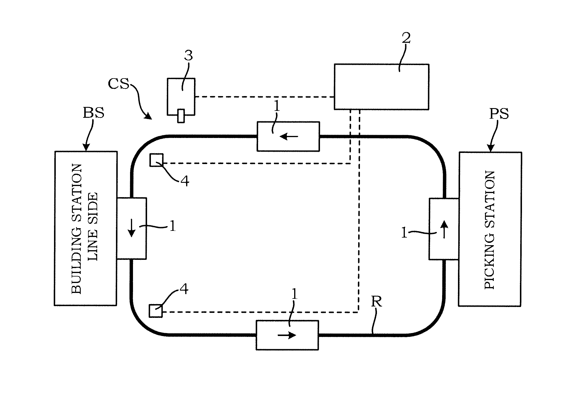
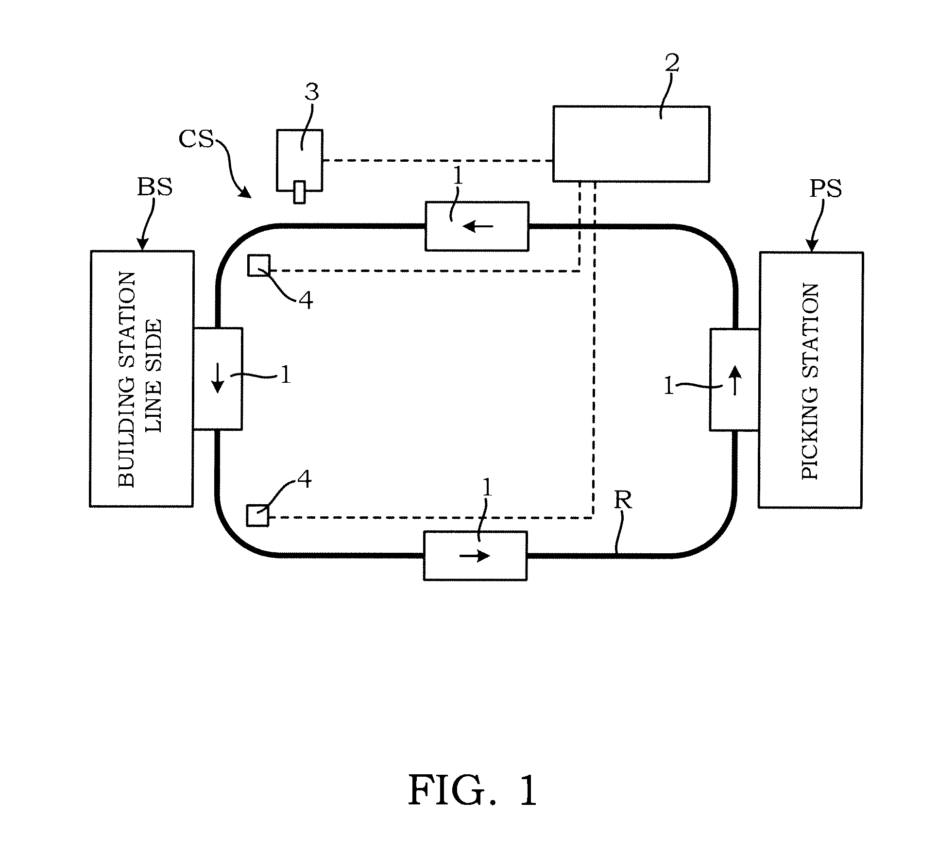
[0016]A traveling course for a transporting process in which automated guided vehicles 1 are utilized is a traveling route R on an orbit set up so as to go through a picking station PS and a building station BS of a production line, for example, as shown in FIG. 1. In the transporting process, it is configured so that the plurality of automated guided vehicles 1 can travel on this traveling route R, and traveling of each of the automated guided vehicles 1 is controlled by a facility-side control device 2.

[0017]The automated guided vehicle 1 repeats circulative traveling in which parts required at the building station BS are loaded onto the automated guided vehicle 1 at the picking station PS, the automated guided vehicle 1 travels on the traveling route R to convey the parts to the building station BS, the parts loaded at the picking station PS are unloaded, and th...


PUM


Abstract

A system for managing charging of each of a plurality of automated guided vehicles that travels on an orbiting route in an unmanned manner using a battery mounted thereon as a driving source, in which the battery is charged at a charging station installed at a predetermined position on the orbiting route, includes: an after-charging voltage recording unit for recording a voltage after charging at the charging station for each of the automated guided vehicles; a charge priority setting unit for setting up charge priority of each of the automated guided vehicles on the basis of voltage values of voltages after charging recorded in the after-charging voltage recording unit; and a charging target value setting unit for setting up a charging target value of each of the automated guided vehicles on the basis of the charge priorities set up by the charge priority setting unit.

Description

TECHNICAL FIELD[0001]The present invention relates to a charge managing system for an automated guided vehicle that travels in an unmanned manner using an electric power of a battery mounted thereon as a driving source and carries out charging to a battery mounted on the vehicle at a charging station.BACKGROUND ART[0002]An automated guided vehicle of JP2007-74800A mounts a Nickel-Metal Hydride battery or Lithium-ion battery, which can be used even in the case of partially charging and discharging, thereon as a battery. In this automated guided vehicle, charging is started when a remaining capacity of the battery becomes a charging start capacity, and the charging is stopped when the remaining capacity reaches a charging stop capacity.SUMMARY OF THE INVENTION[0003]Now, it is common to use a plurality of automated guided vehicles in an assembly production line so as to travel on a traveling route on which assembling parts are loaded at a picking station, the assembling parts are trans...

Claims


Application Information

Patent Timeline
Patent Type & Authority Applications(United States)
IPC IPC(8): B60L11/18G05D1/00B62D65/02B60L3/12
CPCB60L11/1862B60L11/1824B62D65/022G05D1/0088B60L3/12H02J7/0021H02J7/0027H02J7/0026G05B2219/31004H02J7/00036Y02T90/12Y02T10/7072B60L58/13H02J2310/48Y02T10/70H02J7/0013H02J7/0048H02J7/0042H02J7/00306Y02T90/14B60L53/30H02J7/00302
Inventor FUKUI, TOSHIHITOHIRAYAMA, MITSURU
Owner NISSAN MOTOR CO LTD
Why Eureka
Try Eureka