Quantum supercapacitor

a supercapacitor and quantum technology, applied in the field of quantum supercapacitors, can solve the problems of reducing the specific energy accumulated, forming an electron avalanche, and destroying the material of the dielectric, so as to improve the power characteristics of the capacitor, the operation speed, and the storage time of the charge.

Inactive Publication Date: 2007-03-20
ILYANOK ALEXANDR MIKHAILOVICH
View PDF11 Cites 5 Cited by
  • Summary
  • Abstract
  • Description
  • Claims
  • Application Information

AI Technical Summary

Benefits of technology

[0008]The essence of the invention is the improvement of the power characteristics of capacitors, their operating speed, creation of the capacitor having small leakage current and long storage time of a charge, and also unlimited number of recharging cycles.

Problems solved by technology

On the way they have multitudinous impacts that result in the formation of an electron avalanche, i.e., disruption.
Besides, there is an opportunity of activization of electrons, taking place in the material of the dielectric which also participate in avalanche disruption.
Furthermore, with the increase of dielectric thickness there is a so-called bulk effect, i.e., disruptive voltage of the dielectric is reduced steeply, that results in reduction of accumulated specific energy.
The avalanche disruption results in the destruction of the material of the dielectric and the formation of a defective channel which is not restored.
In result, the capacitor fails.

Method used


Image

  • Quantum supercapacitor
  • Quantum supercapacitor
  • Quantum supercapacitor

Examples


Embodiment Construction

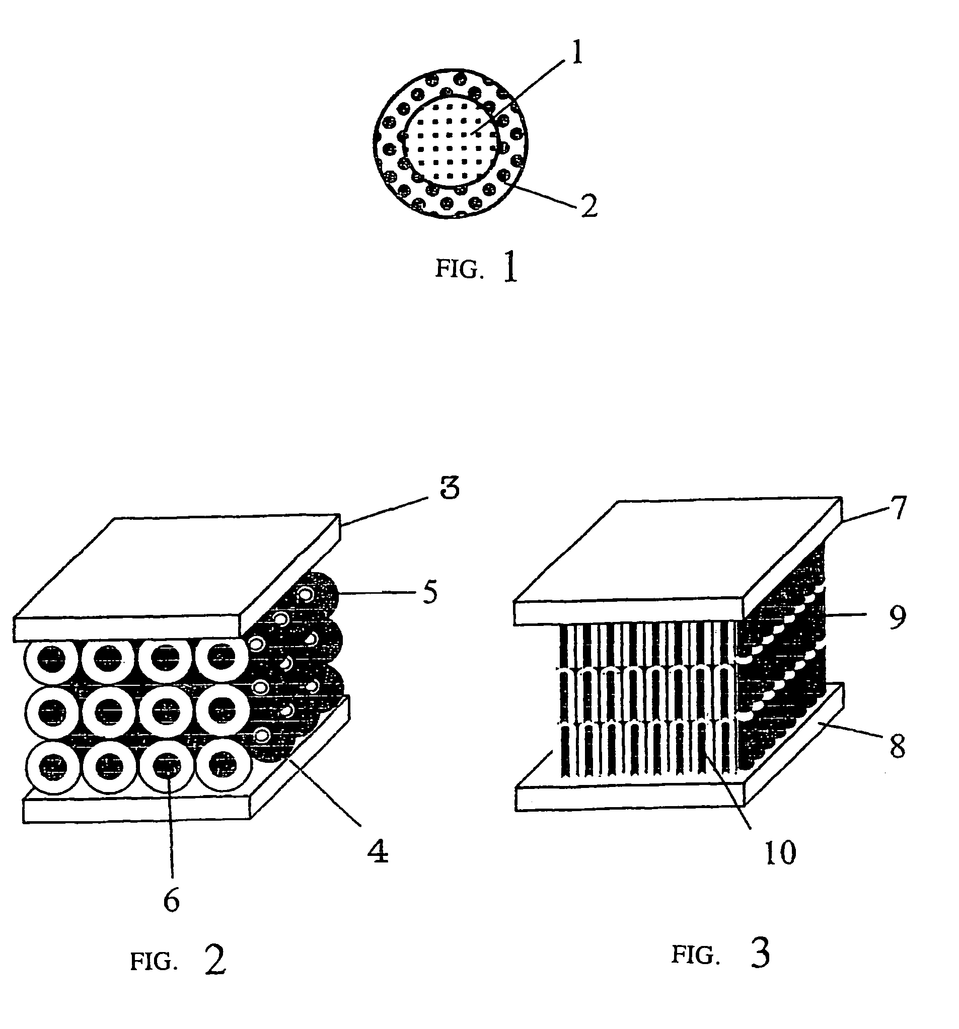
[0049]On FIG. 1 the typical nanoelement of the quantum supercapacitors is represented with a central-symmetric cluster 1 and a tunnel-transparent shell 2. Clusters can be axis-symmetric. It is important, that the resonant conditions of formation in them of a ring wave of electron are carried out.

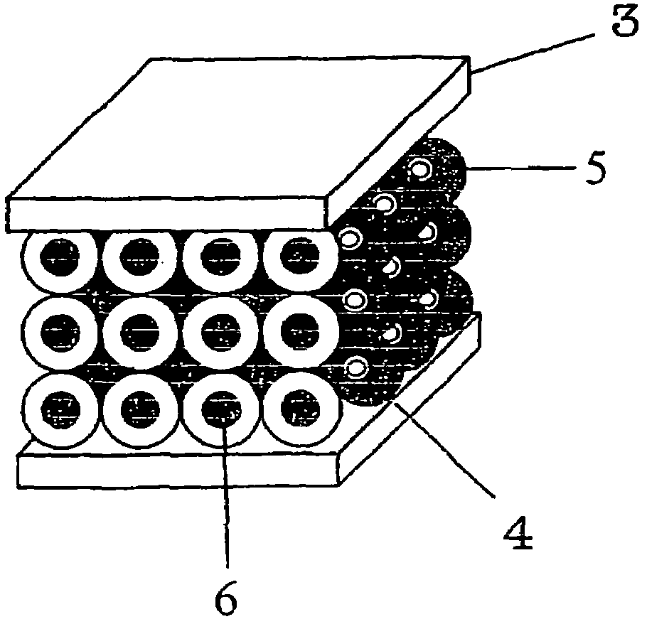
[0050]On FIG. 2 one of the variants of the quantum superccapacitors is represented agrees to the present invention with conducting electrodes 3, 4; tunnel-transparent shell of cluster 5; and central-symmetric cavity in cluster 6. Cluster cavity 6 can be filled with an appropriate material or gas for creation of the formation conditions of the ring resonant electron. Tunnel-transparent shell 5 divides clusters among themselves and creates conditions of motion of electrons as a homogeneous wave from the cathode to the anode. The anode and cathode position can be interchanged, i.e., the capacitor is not polar.

[0051]On FIG. 3 another variant of the quantum superccapacitor is represented with con...


PUM


Abstract

A quantum supercapacitor having nanostrucutured material located between electrodes. The material includes clusters with tunnel-transparent gaps. The clusters have sizes within the range of 7.2517 nm≦r≦29.0068 nm, at which the resonant characteristics of the electron are exhibited. The size is determined by the circular radius of the electronic wave according to the formula r0= / (meα2c)=7.2517 nm (Plank constant , electron mass me, fine structure constant α=1 / 137,036, speed of light c). The cluster size is set within the range r0≦4r0; the width of the tunnel-transparent gap being ≦r0=7.2517 nm. The energy in the supercapacitor is stored by means of controlled breakthrough of the material—a dielectric, with subsequent restoring thereof. The energy is stored uniformly along the whole volume of the material due to the resonant coupling of the electrons on the cluster. The maximum stored specific energy stored is 1.66 MJ / kg.

Description

BACKGROUND OF THE INVENTION[0001]1. Field of the Invention[0002]The invention relates to the field of electronics and electrotechnology and can be used in production of capacitors for creation of elements (cells) of memory for integrated microcircuits, in high-Q contours, in decoupling elements, and in reserve power supplies. Such memory cells can be used as sources of current for a mobile communication facility, in energy installation of an electric vehicle, and also for buffer accumulation of electrical energy with high specific density on the order of 1–1.5 MJ / kg.[0003]2. Background Art[0004]Electrical capacitors having a large specific capacity on the base of solid dielectrics are known. For example the capacitor on BaTiO3 dielectrics have large permittivity ∈>1000 and specific capacity of about 0.3 F / cm3. However, in the majority of the power applications such specific capacity is not enough. To increase specific capacity different methods are applied. A most effective metho...

Claims


Application Information

Patent Timeline
Patent Type & Authority Patents(United States)
IPC IPC(8): H01L29/76H01L29/12
CPCB82Y10/00H01G4/06H01L29/127H01G4/08Y10S977/773Y02E60/13
Inventor ILYANOK, ALEXANDR MIKHAILOVICH
Owner ILYANOK ALEXANDR MIKHAILOVICH
Why Eureka
Try Eureka