System for improving the energy efficiency in hydraulic systems, piston accumulator and pressure accumulator provided for such a system

Active Publication Date: 2017-04-25
HYDAC FLUITECHNIK GMBH
View PDF5 Cites 5 Cited by
  • Summary
  • Abstract
  • Description
  • Claims
  • Application Information

AI Technical Summary

Benefits of technology

[0005]This object is basically achieved according to the invention by a system having, as an essential feature of the invention, at least one hydraulic accumulator that offers a preferably discontinuous option for adjustment. The accumulator provides a plurality of pressure chambers, which are adjacent to effective surfaces on the fluid side of the accumulator piston having different sizes. An adjustment assembly is provided, which connects a selected pressure chamber or a plurality of selected pressure chambers of the piston accumulator to the actuator as a function of the respective pressure level prevailing on the gas side of the piston accumulator. This selection results in the possibility of recycling energy independent of the pre-charge pressure on the gas side of the accumulator, and independent of the respective load pressure, because the

Problems solved by technology

Selecting a small surface at a constant volume flow results in a short charge time for the accumu

Method used


Image

  • System for improving the energy efficiency in hydraulic systems, piston accumulator and pressure accumulator provided for such a system
  • System for improving the energy efficiency in hydraulic systems, piston accumulator and pressure accumulator provided for such a system
  • System for improving the energy efficiency in hydraulic systems, piston accumulator and pressure accumulator provided for such a system

Examples


Example

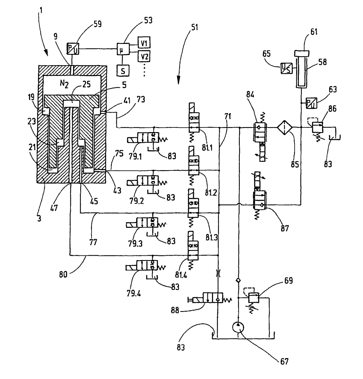
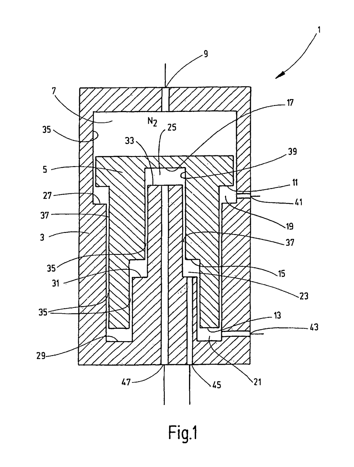
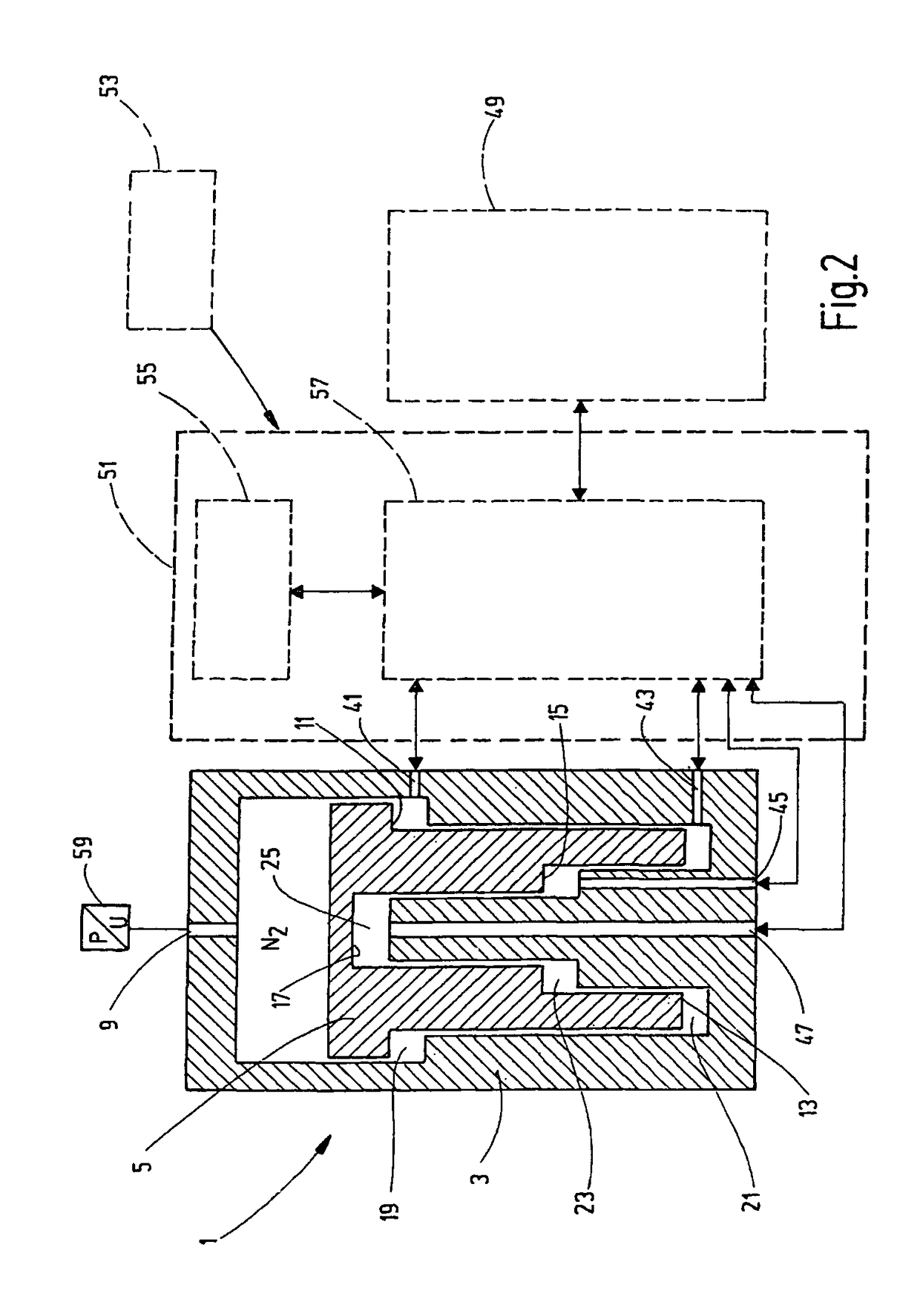
[0034]The schematic, simplified illustration of a hydropneumatic piston accumulator 1 shown in FIG. 1 has an accumulator piston 5 that is guided in an accumulator housing 3 such that the accumulator piston 5 is axially movable. The accumulator piston separates a gas side 7 on which a filling connector 9 is located, from pressure chambers on the fluid side in an accumulator housing 3. The accumulator piston 5 is designed in the manner of a stepped piston in such a way that the accumulator piston, in cooperation with correspondingly stepped sections of the of the accumulator housing 3, delimits fluid-side pressure chambers 19, 21, 23 and 25. These chambers are adjacent to effective surfaces having different sizes on the fluid side of the accumulator piston 5. In FIG. 1, these effective surfaces 11, 13, 15 and 17 are arranged in sequence from the smallest surface to the largest surface. The effective surfaces 11, 13 and 15 are thereby each formed by annular surfaces that are concentric...


PUM


Abstract

A hydraulic system includes an actuator operating as a consumer of hydraulic energy and as a generator of hydraulic energy in different operating states, and includes a hydraulic accumulator (1). In an operating state of the actuator (49), the accumulator can be charged by the actuator for storing energy. In a different operating state, the accumulator can be discharged for delivering energy to the actuator (49). The hydraulic accumulator is an adjustable hydropneumatic piston accumulator having a plurality of pressure chambers (19, 21, 23, 25) adjoining effective surfaces (11, 13, 15, 17) of different sizes on the fluid side of the accumulator piston (5). An adjusting arrangement (51) connects a selected pressure chamber (19, 21, 23, 25) or a plurality of selected pressure chambers (19, 21, 23, 25) of the piston accumulator (1) to the actuator (49) as a function of the pressure level that prevails on the gas side of the piston accumulator (1) and on the actuator (49).

Description

FIELD OF THE INVENTION[0001]The invention relates to a system for improving the energy efficiency in hydraulic systems, having an actuator. In one operating state, the actuator functions as a consumer of hydraulic energy. In another operating state, the actuator functions as a generator of hydraulic energy. A hydraulic accumulator, when in one operating state of the actuator, can be charged by the actuator for the storage of energy. When in another operating state, the accumulator can be discharged for the delivery of energy to the actuator. In addition, the invention relates to a hydropneumatic piston accumulator for use with such a system and a pressure accumulator.BACKGROUND OF THE INVENTION[0002]Given the increasing scarcity of resources and the increased efforts to save energy associated therewith, systems of the above type are becoming increasingly important. Such systems are used in hydraulic devices and systems for example, in which actuators in the form of working cylinders...

Claims


Application Information

Patent Timeline
IPC IPC(8): F16D31/02F15B21/14F15B1/02F15B1/24E02F9/22
CPCF15B21/14E02F9/2217F15B1/024F15B1/24F15B2201/205F15B2201/31F15B2201/413F15B2201/51F15B2211/20569F15B2211/212F15B2211/625F15B2211/633F15B2211/6309F15B2211/6336F15B2211/7052F15B2211/88Y02E60/15Y02E60/16
Inventor SCHULZ, FRANKBRUCK, PETER
Owner HYDAC FLUITECHNIK GMBH
Why Eureka
Try Eureka