Three-dimensional shaped solid dosimeter and method of use

Inactive Publication Date: 2007-01-25
ADAMOVICS JOHN A
View PDF40 Cites 16 Cited by
  • Summary
  • Abstract
  • Description
  • Claims
  • Application Information

AI Technical Summary

Benefits of technology

[0074] An advantage of the present invention is that it provides a 3D dosimetric map formed by irradiation which exhibits a high degree of resolution. In general, an advantage of the present invention is that it provides a 3D dosimetric map formed by irradiation which exhibits a high degree of image stability and integrity. Another advantage of the present invention is that it provides a 3D dosimetric map formed by irradiation which upon analysis by one of several means known to those skilled in the art accurately reconstructs the irradiation event. Another advantage of the present invention is that it provides a substantially transparent plastic dosimeter which can be fabricated into any shape, is homogeneous across all dimensions, and can be irradiated and analyzed without the aid of a container. Another advantage of the present invention is that it provides a substantially transparent plastic dosimeter which contains a 3D dosimetric map formed by irradiation which is stabilized loss of data due to premature fading, bleaching, or whitening of the contained image. Another advantage of the present invention is that it provides a substantially transparent plastic dosimeter which contains a 3D dosimetric map formed by irradiation which is stabilized by elements of the invention against loss of data due to unintended changes in the optical attributes of the polymeric media due to exposure to the environment. Another advantage of the present invention is that it provides a robust and safe process of manufacture which can be practiced without the need to exclude oxygen. Another advantage of the present invention is that it provides a dosimeter capable of accurately measuring the absolute dose of radiation.
[0075] The invention can be further illustrated by the following examples thereof, although it will be understood that these examples are included merely for purposes of illustration and are not intended to limit the scope of the invention unless otherwise specifically indicated. All percentages, ratios, and parts herein, in the Specification, Examples, and Claims, are by weight and are approximations unless otherwise stated. EXAMPLES
[0076] Materials used were obtained from the following manufacturers: Crystal Clear 206 Part A, 200 Part B, 220 Part A, 220 Part B from Smooth-On, Inc., Easton, Pa.; carbon tetrachloride, chloroform, bromochloromethane, tribromopropane, dibromohexane, benzoylmethylene blue, benzoyl peroxide, dichloromethane, butyl acetate, 4,4′-methylene bis(cyclohexyl isocyanate) (HMDI), azobis(isobutyrylnitrile) (AIBN), crystal violet lactone, leuco crystal violet, and leucomalachite green from Sigma-Aldrich, St. Louis, Mo.; Poly-Optic 14-70 Part A, Poly-Optic 14-70 Part B, and Optic Part 14X catalyst from PolyTech Development Corp, Easton, Pa.; Andur prepolymers (Andur AL62DP) from Anderson Development Co., Adrian, Mich.; Aliphatic Isocyanate Prepolymer and Z-8002 Polyol from Development Associates, North Kingstown, R.I.; Tolonate XIDT-70B polyisocyanate trimer from Rhodia PPMC; Tone 32B8 Polyol from Dow Chemical Co.; ConOptic 2020 Part A and ConOptic 2020 Part B from Cytec; Hisorb 944 and Hisorb 328 from LG Chem, Ltd.

Problems solved by technology

It was found that several dyes, when admitted into a polymer of a polyurethane plastic matrix, gave unacceptably high background color (before irradiation) or were incompatible with the polymer components.
Other dyes, although soluble in the polyurethane, gave poor color transformation parameters upon irradiation.

Method used


Image

  • Three-dimensional shaped solid dosimeter and method of use
  • Three-dimensional shaped solid dosimeter and method of use
  • Three-dimensional shaped solid dosimeter and method of use

Examples


example 1

[0077] Crystal Clear 206 Part A (250 g), Crystal Clear 206 Part B (200 g), carbon tetrachloride (180 g), Optic Part 14X catalyst (0.6 ml) and leucomalachite green (16 g) were blended thoroughly in a 1000 ml polyethylene beaker until the mixture was homogeneous. The mixture was then immediately poured into molds. The molds were either glass or polyethylene 30 ml vials. The filled molds were then placed under 60 psi pressure and maintained at 25° C. for 18 hours. This was achieved by arranging the molds within a pressure pot of the appropriate size and pressurizing with a compressor pump. At the end of this period, the solid dosimeters formed in polyethylene vials were removed from the molds.

example 2

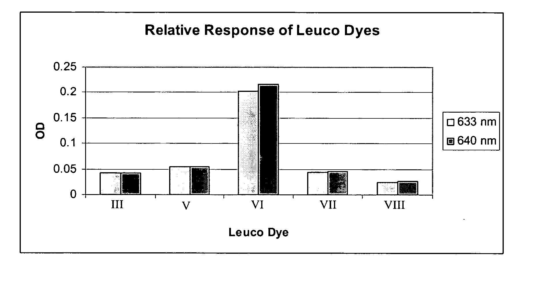
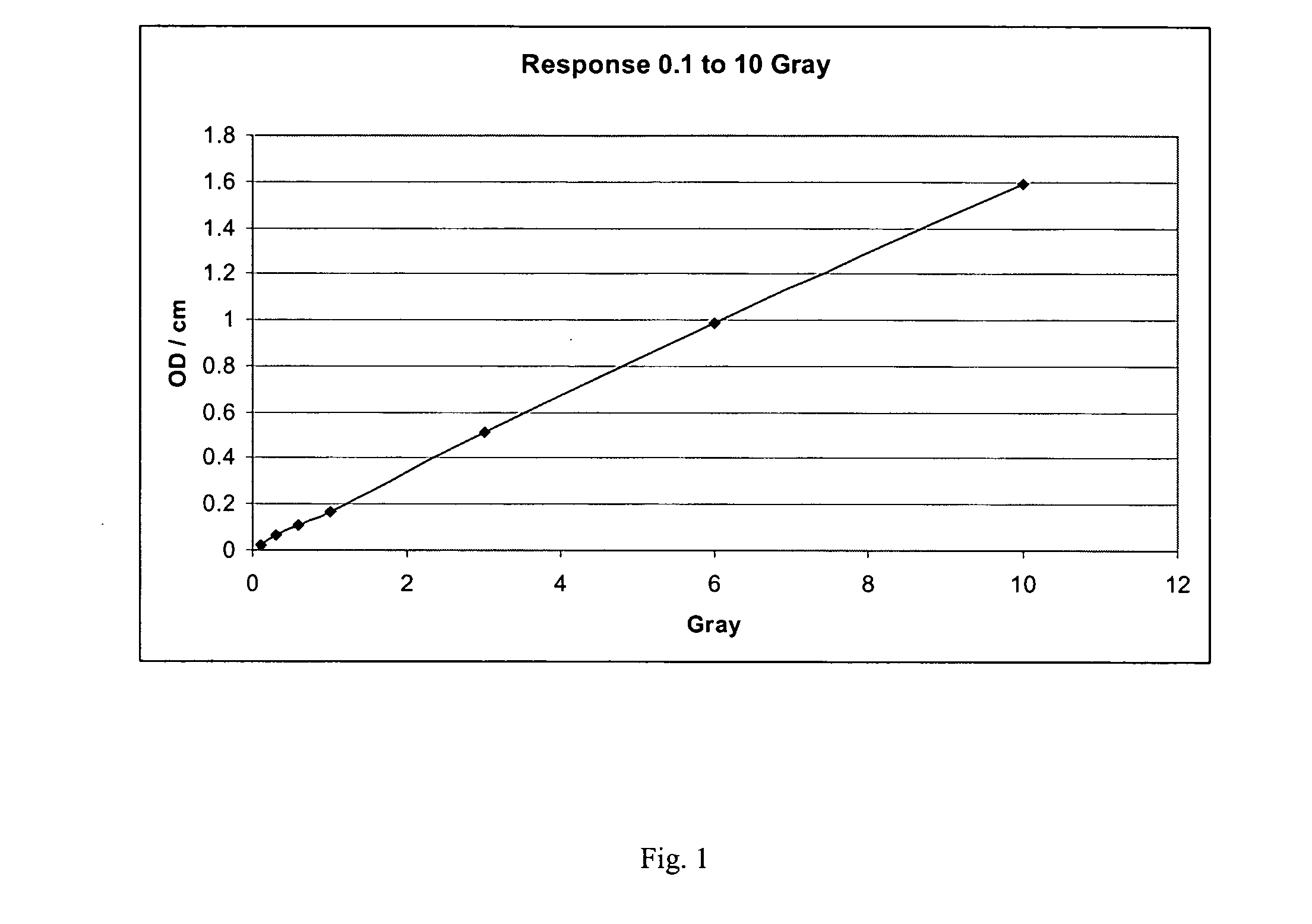
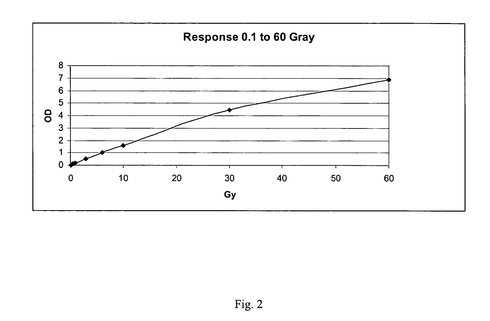
[0078] In order to assess the dose response of the conversion of the leuco dye of the present invention to the amount of radiation encountered, dosimeters as described in Example 1 were subjected to graded doses of 145 kVp x-rays at three different dose rates, 0.66 Gy / min, 2.17 Gy / min, and 4.4 Gy / min, using Torrex 150D X-ray unit (EG&G, Long Beach, Calif.). The irradiated dosimeters were evaluated using the commercially available OCT-OPUS™ CT scanner (MGS Research, Inc., Madison, Conn.). In this analysis the conversion of leucomalachite green to the colored species is detected as an increase in optical density at 633 nm, a wavelength at which the leuco dye does not absorb. The transformation of leucomalachite green to its colored form was linear with dose and independent of dose rate.

example 3

[0079] 4,4′-methylene bis(cyclohexyl isocyanate) (HMDI) (94 g), carbon tetrachloride (90 g), Crystal Clear 206 Part B (80 g), leucomalachite green (4.0 g) and Optic Part 14X catalyst (1.0 ml) were blended thoroughly in a 1000 ml polyethylene beaker. The mixture was then immediately poured into mold fabricated from a 500 ml cylindrical polyethylene beaker. The filled mold was pressurized as in Example 1 and incubated at 25° C. for 20 hours. The solid dosimeter was then removed from the mold.


PUM


Abstract

The invention relates to a solid plastic three-dimensional dosimeter which is useful in treatment planning, optimization of the radiation field, dose verification, dose validation, commissioning, and quality assurance of complex radiotherapeutic procedures. Dosimeters of the invention can be formed in any clinically relevant shape, and contain a reporter leuco dye which forms a colored image upon irradiation.

Description

CROSS REFERENCE TO RELATED APPLICATION [0001] This application is a continuation in part of U.S. patent application Ser. No. 10 / 790,280, filed Mar. 1, 2004, the entirety of which is hereby incorporated by reference into this application.BACKGROUND OF THE INVENTION [0002] 1. Field of the Invention [0003] The present invention relates to dosimeters and in particular to a three-dimensional shaped solid dosimeter and method of use. [0004] 2. Description of Related Art [0005] In the field of radiotherapy of human cancer it is important to plan the intensity, duration, dose, and target volume of radiation to achieve optimal impact upon the target tumor and minimal exposure of nearby normal tissue. Recently, complex radiotherapy regimens such as three-dimensional conformal radiotherapy (3DCRT) and intensity-modulated radiotherapy (IMRT) have found increased use in radiation oncology. The IMRT technique is a method which delivers doses of radiation to conform to irregularly shaped tumor vol...

Claims


Application Information

Patent Timeline
IPC IPC(8): H01L21/00
CPCA61N5/1048G01T1/04A61N5/1075A61N5/1071
Inventor ADAMOVICS, JOHN A.
Owner ADAMOVICS JOHN A
Why Eureka
Try Eureka