System for improving the energy efficiency in hydraulic systems

Active Publication Date: 2019-06-18
HYDAC FLUITECHNIK GMBH
View PDF11 Cites 1 Cited by
  • Summary
  • Abstract
  • Description
  • Claims
  • Application Information

AI Technical Summary

Benefits of technology

This invention is a system that uses a hydraulic accumulator with pressure chambers to adjust pressure and recycle energy. The accumulator can be connected to a working cylinder based on the pressure levels and the load pressure. The system has a control logic unit that uses sensor data to decide how the accumulator should be charged or discharged, allowing for optimal energy conversion for different operating states. The user can also set presets to influence the system's load characteristic. The technical effect of this invention is improved energy conversion and control over the system's load characteristics.

Problems solved by technology

If a small surface is selected at a constant volume flow for example, this situation will result in a short loading time of the accumulator.
If a large surface is selected at a constant volume flow, this situation will result in a longer loading time.

Method used


Image

  • System for improving the energy efficiency in hydraulic systems
  • System for improving the energy efficiency in hydraulic systems
  • System for improving the energy efficiency in hydraulic systems

Examples


Embodiment Construction

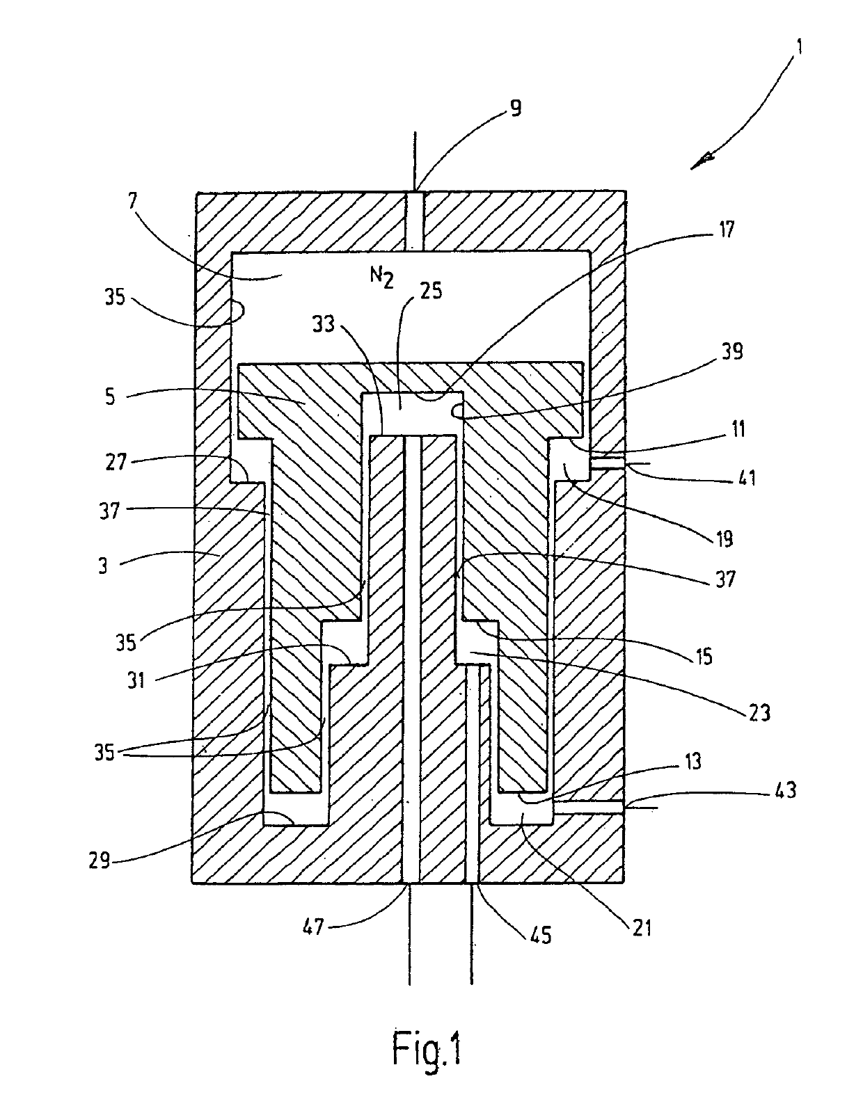
[0020]The hydropneumatic piston accumulator 1, which is shown in a schematic, simplified depiction in FIG. 1, has an accumulator piston 5 that is axially movably guided in an accumulator housing 3. The accumulator piston 5 separates a gas side 7, on which a filling port 9 is located, from fluid-side pressure chambers in the accumulator housing 3. The accumulator piston 5 is configured in the manner of a step piston such that, in combination with corresponding stepped portions of the accumulator housing 3, the accumulator piston delimits fluid-side pressure chambers 19, 21, 23 and 25, which are adjacent to active surfaces 11, 13, 15 and 17 of different sizes on the fluid side of the accumulator piston 5. In FIG. 1, these active surfaces 11, 13, 15 and 17 are arranged in order from the largest surface to the smallest surface. Here, the active surfaces 11, 13 and 15 are each formed by annular surfaces disposed concentrically relative to the longitudinal axis, which surfaces surround th...


PUM


Abstract

A system for hydraulic systems includes a working cylinder (58) which operates as a consumer of hydraulic energy or as a generator of hydraulic energy. A hydraulic accumulator (1) can be charged by the working cylinder for storing energy and can be discharged for delivering energy to the working cylinder (58). One hydraulic accumulator is provided in the form of an adjustable hydropneumatic piston accumulator (1), in which with a plurality of pressure chambers (19, 21, 23, 25) adjoining effective surfaces (11, 13, 15, 17) of different sizes are on the fluid side of the accumulator piston (5). An adjusting arrangement (51) connects a selected pressure chamber (19, 21, 23, 25) or a plurality of selected pressure chambers (19, 21, 23, 25) of the piston accumulator (1) to the working cylinder (58) as a function of the pressure level that prevails respectively on the gas side of the piston accumulator (1) and on the working cylinder (58).

Description

FIELD OF THE INVENTION[0001]The invention relates to a system for improving the energy efficiency in hydraulic systems. At least one working cylinder operates as a consumer of hydraulic energy in one operating state and as a generator of hydraulic energy in another operating state. A hydraulic accumulator can be charged by the working cylinder for storing energy in one operating state of the working cylinder, and can be discharged for delivering energy to the working cylinder in another operating state.BACKGROUND OF THE INVENTION[0002]Given the increasing scarcity of resources and the increased efforts to save energy associated therewith, systems of the type described above are becoming increasingly important. For this reason, such systems are frequently used in hydraulic equipment and systems, in which actuators in the form of working cylinders are provided. In the case of raising and lowering applications, the potential energy of a load that has been lifted can thereby be converte...

Claims


Application Information

Patent Timeline
IPC IPC(8): F15B1/02F15B3/00F15B21/14F15B11/032F15B11/072F15B1/24
CPCF15B3/00F15B1/024F15B11/032F15B11/072F15B21/14F15B1/24F15B2201/205F15B2201/31F15B2201/41F15B2211/216F15B2211/30525F15B2211/5152
Inventor SCHULZ, FRANKBRUCK, PETER
Owner HYDAC FLUITECHNIK GMBH
Why Eureka
Try Eureka