Cooperative control system and cooperative control method of IT device and storage battery

A technology of cooperative control and storage battery, which is applied in battery circuit devices, current collectors, electric vehicles, etc., and can solve the problem of having to place a generator without a generator.

Inactive Publication Date: 2013-06-26
HITACHI LTD
View PDF3 Cites 4 Cited by
  • Summary
  • Abstract
  • Description
  • Claims
  • Application Information

AI Technical Summary

Problems solved by technology

Set generator locations in the building to run generators, b

Method used


Image

  • Cooperative control system and cooperative control method of IT device and storage battery
  • Cooperative control system and cooperative control method of IT device and storage battery
  • Cooperative control system and cooperative control method of IT device and storage battery

Examples


Embodiment Construction

[0032] Embodiments for implementing the present invention will be described in detail based on the drawings. In addition, in all the figures for explaining the form for carrying out the invention, the same name and code|symbol are attached|subjected to the element which has the same function, and the repeated description is abbreviate|omitted.

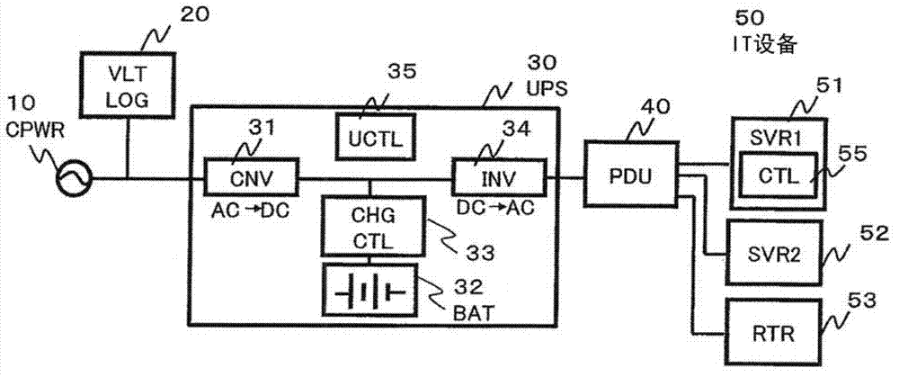
[0033] figure 1The main part of the system for performing cooperative control of IT equipment and a storage battery according to an example of this invention is shown in . Wiring represents a system of power. Electric power is provided from a power generation by a commercial power supply CPWR10. A voltage logger VLTLOG 20 is installed at a position where the voltage of a commercial power supply can be measured. The voltage recorder 20 can record voltages in time series or when events occur, and can measure surges (swells), sags, momentary outages, etc. from voltage values, and can also measure power outages. An uninterruptible powe...


PUM


Abstract

The invention provides a cooperative control system and a cooperative control method of IT devices and storage batteries. The characteristics (time, frequency, and spacing) of coming shutdown is judged in advance, the presumed shutdown can be controlled through the cooperation of the IT devices and an uninterrupted power device having the storage batteries, thereby realizing the high efficiency of the charging and discharging of the storage batteries. The cooperative control system includes a commercial power supply (10), a voltage recorder (20) for measuring the voltage of the commercial power supply, an uninterrupted power device (30) connecting with a plurality of storage batteries (32), a power supply connector (40) equipped with a power determining mechanism, and a plurality of IT devices (50) including servers (51) connecting with the power supply connector. Controlling parts (55) inside the servers predict the continuous time of the future shutdown, the power limit value of the IT devices is figured out based on the remain of the storage batteries and the predicted shutdown time, and the power of the IT devices is controlled to satisfy the power limit value.

Description

technical field [0001] The present invention relates to a system including IT equipment and a large-capacity storage battery, and more particularly to a cooperative control system of IT equipment and storage battery suitable for efficiently using the storage battery and stably operating the IT equipment for a long time. Background technique [0002] In areas where the basic equipment of the power grid is insufficient, power outages occur frequently. Therefore, a method is adopted in which a generator is installed in a building, and the generator is operated during a power outage to supply electric power in the building. In the server room, an array of lead storage batteries required for several hours of repair of the generator is further installed in case of failure of the generator, and power is supplied to the server and client PCs. Generally, the storage battery array employs a system in which the capacity of the lead storage battery of an uninterruptible power supply (U...

Claims


Application Information

Patent Timeline
IPC IPC(8): H02J7/00
Inventor 山田哲也松村忠幸
Owner HITACHI LTD
Why Eureka
Try Eureka