Reciprocating saw

a reciprocating saw and drive mechanism technology, applied in the field of reciprocating saw drive mechanism, can solve the problems of complex and expensive incorporation of a counterbalance into prior art mechanical reciprocating devices, such as eccentric drives and wobble plate drives, and other potential failure points, so as to achieve the effect of adding weight, cost, or complexity, without adding significant weight, cost, or expens

Inactive Publication Date: 2005-01-13
MILWAUKEE ELECTRIC TOOL CORP
View PDF36 Cites 12 Cited by
  • Summary
  • Abstract
  • Description
  • Claims
  • Application Information

AI Technical Summary

Benefits of technology

[0005] Incorporation of a counterbalance into prior art mechanical reciprocating devices, such as eccentric drives and wobble plate drives, can be complex and expensive. Further, the introduction of additional mechanisms into the devices can create another potential point of failure. Accordingly, it is an independent object of the present invention to design a saw that provides an improved drive mechanism without necessarily adding weight, cost, or com

Problems solved by technology

Incorporation of a counterbalance into prior art mechanical reciprocating devices, such as eccentric drives and wobble plate drives, can b

Method used


Image

  • Reciprocating saw
  • Reciprocating saw
  • Reciprocating saw

Examples


Embodiment Construction

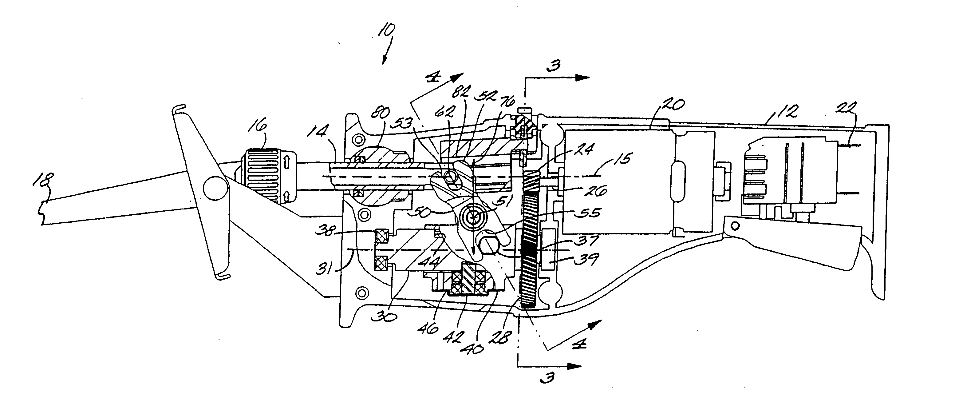
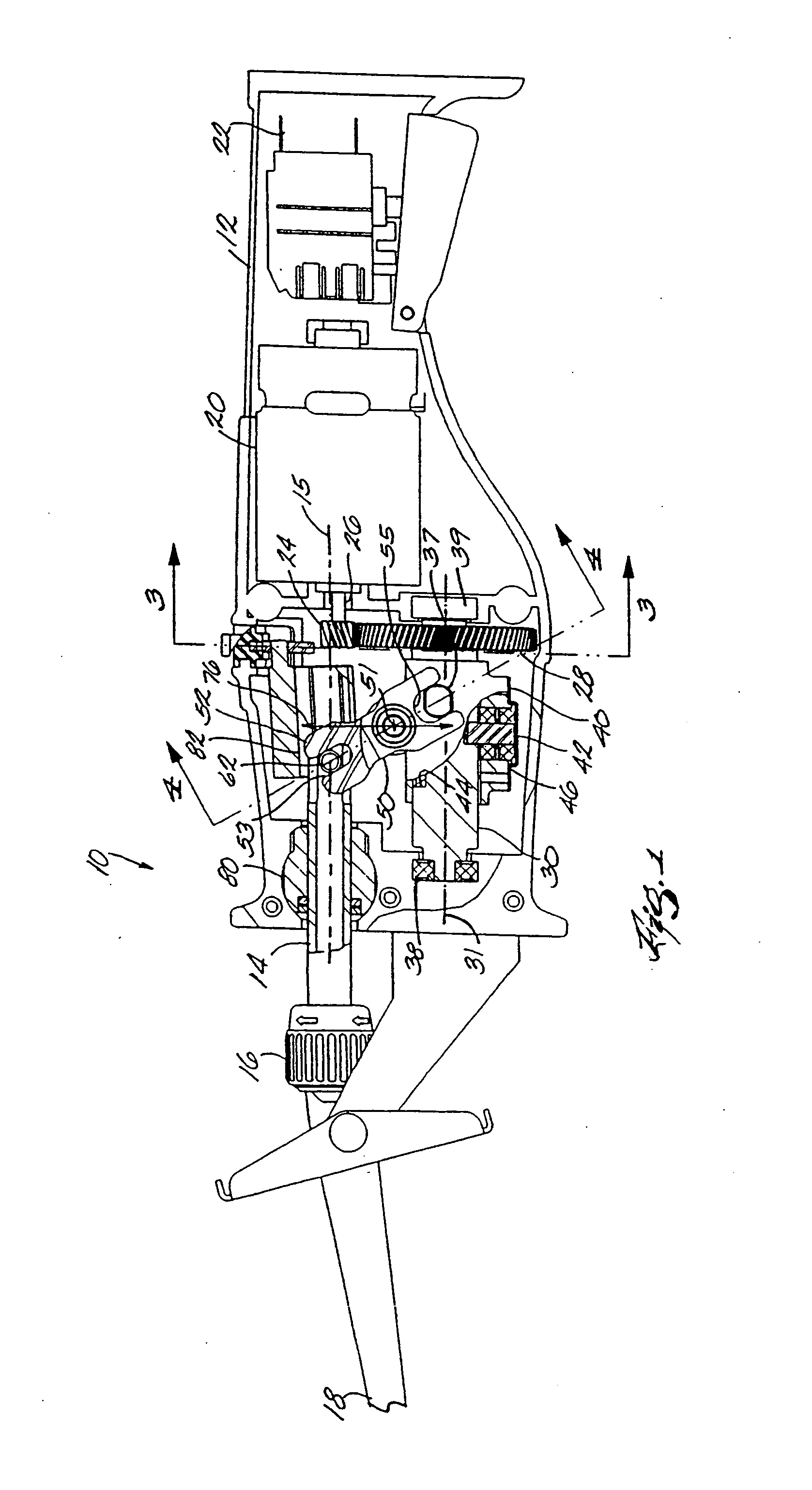
[0030] Referring to the drawings, FIG. 1 shows a reciprocating saw 10 according to the present invention. Some components of the reciprocating saw 10 may be similar or identical to components shown in U.S. patent application Ser. No. 08 / 699,448, filed Aug. 19, 1996, which is herein incorporated by reference.

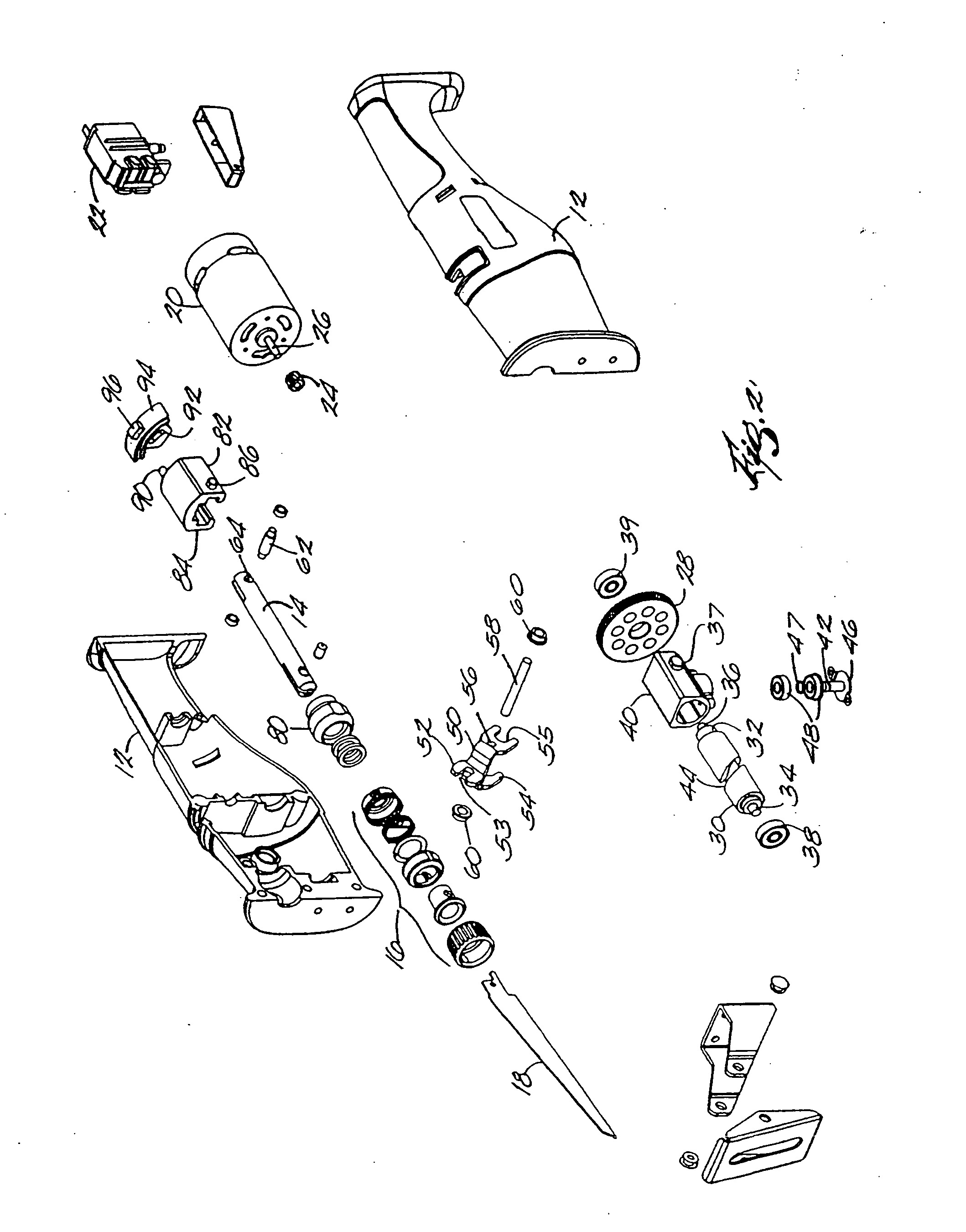
[0031] The reciprocating saw 10 generally includes a housing 12 that is configured to house the drive components at the front end and to fit an operator's hand at the rear end. The housing is split in two halves (FIG. 2), which are combined when the saw 10 is assembled. At the front end of the reciprocating saw 10 is a saw blade 18 mounted to a spindle 14 that reciprocates within the saw 10. Specifically, the saw blade 18 is mounted within a blade clamp 16 at the front end of the spindle 14. Such a blade clamp is shown and described in pending International Application No. PCT / US97 / 03633, which claims the benefit of U.S. Provisional Application Ser. No. 60 / 021,470, both of which...


PUM

PropertyMeasurementUnit
Lengthaaaaaaaaaa
Elastomericaaaaaaaaaa

Abstract

A reciprocating saw including a housing, a motor supported by the housing, a spindle mounted for reciprocation relative to the housing and having a front end for supporting a saw blade, the spindle being movable through a cutting stroke and a return stroke, the cutting stroke having a stroke length, and a pivot body interconnecting the spindle and the motor. The position of the pivot axis of the pivot body may be movable relative to the housing to change the stroke length of the spindle. A shock absorber may be operatively positioned between the motor and the front end of the spindle and may be at least partially mounted within the spindle.

Description

RELATED APPLICATIONS [0001] The present application is a divisional of application Ser. No. 10 / 118,856, filed Apr. 9, 2002, which is a continuation-in-part of application Ser. No. 09 / 832,242, filed Apr. 10, 2001, now U.S. Pat. No. 6,742,267, issued Jun. 1, 2004, which is a continuation-in-part of application Ser. No. 09 / 169,509, filed Oct. 9, 1998, now U.S. Pat. No. 6,212,781, issued Apr. 10, 2001.FIELD OF THE INVENTION [0002] The invention relates to reciprocating saws and, more particularly, to the drive mechanisms of reciprocating saws. BACKGROUND OF THE INVENTION [0003] Reciprocating saws are used to cut a variety of objects, such as metal pipes, wood and drywall. Such saws typically include a housing and a spindle mounted in the housing for reciprocating motion along an axis that is parallel to the longitudinal extent of the spindle. An electric motor provides power to the spindle through a mechanical reciprocating device that converts the rotary motion of a motor shaft to reci...

Claims


Application Information

Patent Timeline
IPC IPC(8): B23D51/16
CPCY10T74/18312B23D51/16Y10T83/05
Inventor MARINKOVICH, DRAGOMIR C.NEITZELL, ROGER D.JAMES, THOMAS P.
Owner MILWAUKEE ELECTRIC TOOL CORP
Why Eureka
Try Eureka