Aircraft wing slat skew detection systems and methods

a technology of wing slats and detection systems, applied in mechanical devices, transportation and packaging, gearing, etc., can solve the problems of other slats, relatively small deflection, and end of slat displacement, and achieve the effect of adding significant weight or cost to the aircra

Active Publication Date: 2017-11-14
THE BOEING CO
View PDF18 Cites 2 Cited by
  • Summary
  • Abstract
  • Description
  • Claims
  • Application Information

AI Technical Summary

Benefits of technology

[0009]In accordance with the present disclosure, example systems and methods are provided that are capable of detecting skew in any wing slat of a practical size, regardless of its location within the wing, and of doing so reliably and without adding significant weight or cost to the aircraft.

Problems solved by technology

However, certain failures of the structural members or the drives of the slats of some types of modern aircraft can result in a condition referred to as “skew,” in which one end of the slat becomes stuck or decoupled from the associated slat drive mechanism during extension or retraction, thereby allowing that end of the slat to become displaced relative to those of the other slats.
Due to the stiffness of the slats, this creates only relatively small deflections when aerodynamic loads are applied to that slat during flight.
However, if this type of failure goes undetected, the slat can become completely disconnected from the aircraft wing, resulting in the loss of the slat, and potentially, a more serious type of failure.
In particular, the loss during flight of slats that are located more outboard on the wing of an aircraft, while aerodynamically undesirable, is not deemed as serious as the loss of the slats located more inboard on the wing, because the former are typically smaller, and will simply fly harmlessly rearward in the slipstream of the aircraft, whereas, the latter, which are typically larger, heavier and located more toward the centerline of the aircraft, could collide with and damage the empennage, i.e., the rudder and / or elevators, of the aircraft, thereby resulting in a more serious loss of aircraft control.

Method used


Image

  • Aircraft wing slat skew detection systems and methods
  • Aircraft wing slat skew detection systems and methods
  • Aircraft wing slat skew detection systems and methods

Examples


Embodiment Construction

[0021]In accordance with the present disclosure, example systems and methods are provided for detecting a leading edge wing slat skew condition in an aircraft reliably and without adding significant weight or cost to the aircraft.

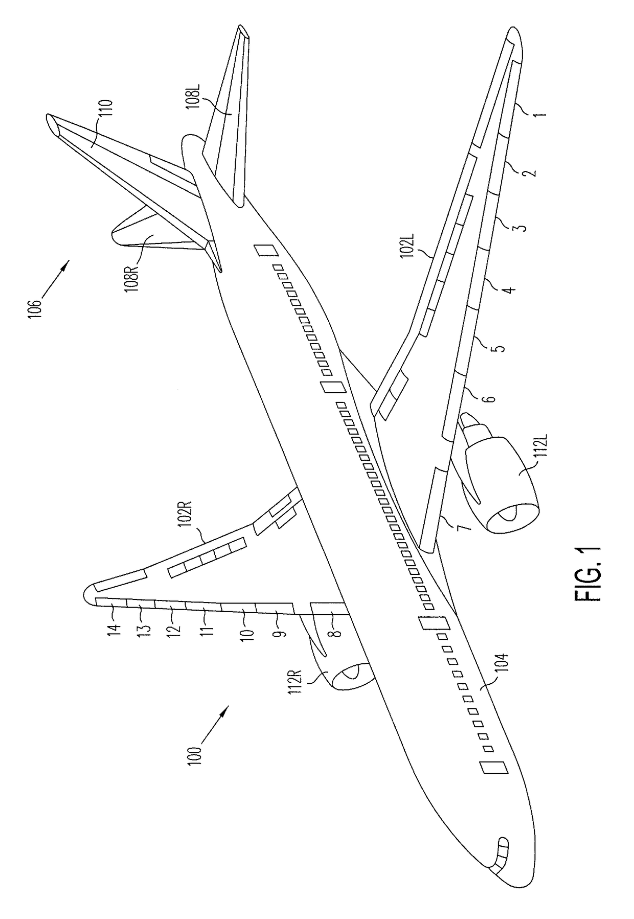
[0022]FIG. 1 is an upper, left side perspective view of a modern commercial jet aircraft 100 equipped with a plurality of slats 1-14, which are disposed along the leading edges of its wings 102L and 102R in pairs, e.g., 1 / 14, 2 / 13, 3 / 12, and so on, that are bilaterally symmetrical with respect to a centerline of the aircraft 100. The aircraft 100 also conventionally includes an elongated fuselage 104 and an empennage 106, comprising a pair of horizontal stabilizers and associated elevators 108L and 108R, and a vertical stabilizer and associated rudder 110.

[0023]Like many passenger jet aircraft today, such as the Boeing 757, 767, 777 and 787 models, the example aircraft 100 of FIG. 1 includes a pair of bilaterally symmetrical, wing-mounted turbofan engines 1...


PUM


Abstract

An apparatus for detecting skew in a slat of an aircraft wing includes an elongated track moveably supported in the wing for longitudinal movement toward and away from a leading edge of the wing. The slat is coupled to a forward end of the track for conjoint movement therewith. An actuator is configured to selectably drive the track and slat between retracted and extended positions relative to the leading edge of the wing. A pinion gear is rotatably mounted in the wing and disposed in rolling engagement with a rack gear disposed on the track, and a sensor is coupled to the pinion gear and configured to sense the longitudinal position of the slat as a function of a rotational position of the pinion gear.

Description

BACKGROUND[0001]1. Technical Field[0002]This disclosure relates to aerodynamic control surfaces of aircraft in general, and more particularly, to systems and methods for detecting aircraft leading-edge wing slat skew.[0003]2. Related Art[0004]Slats are aerodynamic surfaces on the leading edges of the wings of fixed-wing aircraft that, when extended, enable the wing to operate at a higher angle of attack and / or a slower speed without stalling. A higher coefficient of lift is produced as a result of angle of attack and air speed so that, by extending its slats, an aircraft can fly at slower speeds, and / or take off and land within shorter distances. Slats are usually used while landing or performing other low-speed maneuvers that are close to the aircraft's stall speed, but are usually retracted during normal, high-speed flight so as to minimize their aerodynamic drag.[0005]Modern slats are installed at the leading edges of an aircraft's wings in bilaterally symmetrical pairs, and duri...

Claims


Application Information

Patent Timeline
Patent Type & Authority Patents(United States)
IPC IPC(8): F16H19/04B64D45/00
CPCB64D45/0005F16H19/04B64D2045/001
Inventor ANDERSON, RANDALL EUGENE
Owner THE BOEING CO
Why Eureka
Try Eureka