Heat and vibration mounting isolator for a heat shield, heat shield assembly and method of construction thereof

a technology of heat shield and isolator, which is applied in the field of heat shields, can solve the problems of increasing affecting the cooling effect of the vehicle, so as to achieve the effect of reducing the cost and weight of the vehicle, and enhancing the cooling

Inactive Publication Date: 2016-10-27
FEDERAL MOGUL MOTORPARTS LLC
View PDF2 Cites 3 Cited by
  • Summary
  • Abstract
  • Description
  • Claims
  • Application Information

AI Technical Summary

Benefits of technology

[0007]One aspect of the invention provides an isolator for damping heat and vibrations between a heat shield and heat source without a complex construction and without adding significant volume, cost, or weight to the vehicle. The isolator includes a housing surrounding a center opening and extending axially from a first end portion to a second end portion and including an intermediate portion therebetween. The first end portion of the housing extends radially inwardly to form a first annular pocket between the first end portion and the intermediate portion. The second end portion of the housing extends radially outwardly to form a second annular pocket between the second end portion and the intermediate portion. The first annular pocket faces the center opening, and the second annular pocket faces away from the center opening for receiving the heat shield. A washer extends radially from an outer periphery received in the first annular pocket of the housing to the center opening for receiving a fastener to connect the heat shield to the heat source. The washer also includes a plurality of through openings between the outer periphery and the center opening for enhancing vibration dampening and minimizing heat transfer from the heat source to the heat shield.
[0008]Another aspect of the invention includes a heat shield assembly for attachment to a heat source by a fastener. The assembly comprises a heat shield including a through opening presented by an inner periphery; and an isolator received in the through opening of the heat shield for damping heat and vibrations between the heat shield and the heat source. The isolator comprises a housing surrounding a center opening, and the center opening is axially aligned with the through opening of the heat shield. The housing extends axially from a first end portion to a second end portion and includes an intermediate portion therebetween. The first end portion of the housing extends radially inwardly to form a first annular pocket between the first end portion and the intermediate portion. The second end portion of the housing extends radially outwardly to form a second annular pocket between the second end portion and the intermediate portion. The first annular pocket faces the center opening, and the annular pocket faces away from the center opening and receives the inner periphery of the heat shield. A washer extending radially from an outer periphery received in the first annular pocket of the housing to the center opening for receiving the fastener to connect the heat shield to the heat source. The washer includes a plurality of through openings between the outer periphery and the center opening for enhancing vibration dampening and minimizing transfer of heat from the heat source to the heat shield.
[0009]A method of manufacturing an isolator for damping heat and vibrations between a heat shield and heat source is also provided. The method comprises the step of: providing a washer extending radially from an outer periphery to a center opening, the washer including a plurality of through openings between the outer periphery and the center opening for enhancing vibration dampening and minimizing heat transfer from the heat source to the heat shield; and providing a housing surrounding a center opening, the housing extending from a first end portion to a second end portion and including an intermediate portion therebetween. The method further includes bending the housing so that the first end portion extends radially inwardly; disposing the outer periphery of the washer between the first end portion and the intermediate portion of the housing; and bending the housing so that the second end portion extends radially outwardly to form an annular pocket between the second end portion and the intermediate portion, the second annular pocket facing away from the center opening for receiving the heat shield.
[0010]The invention also provides a method of manufacturing a heat shield assembly. The method includes providing a washer extending radially from an outer periphery to a center opening for receiving a fastener to connect the heat shield assembly to the heat source, the washer including a plurality of through openings between the outer periphery and the center opening for enhancing vibration dampening and minimizing heat transfer from the heat source to the heat shield; and providing a housing surrounding a center opening, the housing extending from a first end portion to a second end portion and including an intermediate portion therebetween. The method further includes bending the housing so that the first end portion extends radially inwardly; disposing the outer periphery of the washer between the first end portion and the intermediate portion of the housing; bending the housing so that the second end portion extends radially outwardly; and disposing an inner periphery of a heat shield between the second end portion and the intermediate portion of the housing.

Problems solved by technology

If left unchecked, the heat from the components can have adverse affects on surrounding components.
Known mounting brackets can be complex in construction; relatively bulky and heavy, which in turn adds cost and weight to the vehicle, and further, can allow heat and vibration to affect the performance of the vehicle.

Method used


Image

  • Heat and vibration mounting isolator for a heat shield, heat shield assembly and method of construction thereof
  • Heat and vibration mounting isolator for a heat shield, heat shield assembly and method of construction thereof
  • Heat and vibration mounting isolator for a heat shield, heat shield assembly and method of construction thereof

Examples


Embodiment Construction

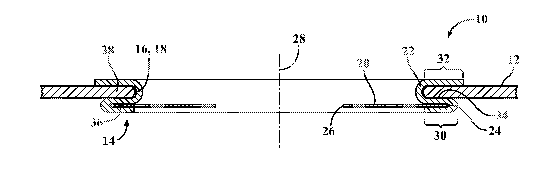
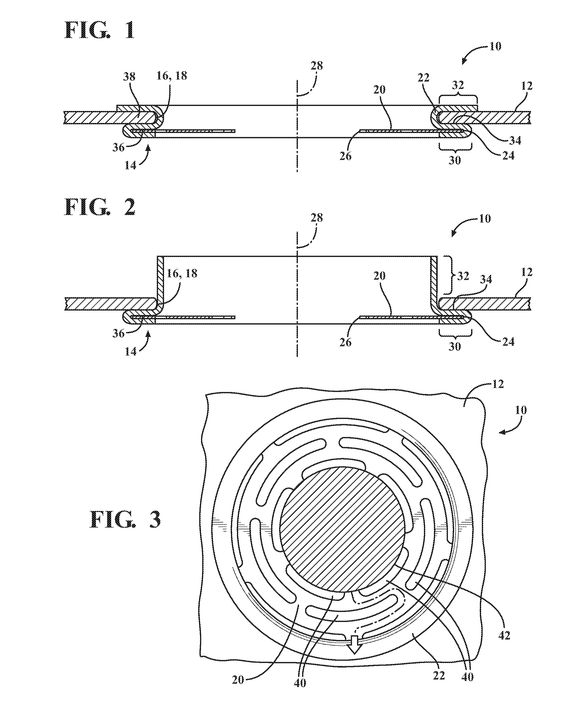
[0044]Referring in more detail to the drawings, FIG. 1-3 (FIG. 2 is partially assembled) show a heat shield assembly, referred to hereafter as assembly 10, constructed in accordance with one presently preferred embodiment of the invention. The assembly 10 is constructed to enhance sound insulation in a manner of vibration dampening, to minimize weight, to minimize conductivity of heat from a heat source throughout the assembly 10, and to occupy as small an envelope as possible. The assembly 10 has a broad array of applicable uses, such as in vehicles having internal combustion engines, construction machinery, and agricultural machinery, by way of example and without limitation. Further, the assembly 10 is economical in manufacture and in assembly and exhibits a long life in use.

[0045]The assembly 10 includes a heat shield 12 and a heat and vibration mounting isolator, referred to hereafter as isolator 14, fixed to one another. The heat shield 12 can be constructed from one or more l...


PUM

PropertyMeasurementUnit
inner diameteraaaaaaaaaa
temperatureaaaaaaaaaa
heataaaaaaaaaa

Abstract

An isolator for damping heat and vibrations between a heat shield and heat source is provided. The isolator includes a housing and a washer. The housing surrounds a center opening and extends axially from a first end portion to a second end portion and includes an intermediate portion therebetween. The housing has a serpentine shape. The first end portion and the intermediate portion of the housing clamp a washer therebetween, and the second end portion and the intermediate portion of the housing clamp the heat shield therebetween. The washer includes a plurality of through openings between an outer periphery and the center opening for enhancing vibration dampening and minimizing heat transfer from the heat source to the heat shield. The isolator optionally includes a collar member disposed along the center opening of the washer to facilitate mounting of the isolator to the heat source.

Description

CROSS-REFERENCE TO RELATED APPLICATION[0001]This U.S. Utility patent application claims priority to U.S. Provisional Patent Application No. 62 / 152,730, filed Apr. 24, 2015, and U.S. Provisional Patent Application No. 62 / 260,039, filed Nov. 25, 2015, the entire contents of which are incorporated herein by reference.BACKGROUND OF THE INVENTION[0002]1. Technical Field[0003]This invention relates generally to heat shields, and more particularly to a mounting and vibration dampening apparatus for mounting a heat shield.[0004]2. Related Art[0005]Vehicles and other equipment that operate via an internal combustion engine contain various components that create extremely high temperature heat. If left unchecked, the heat from the components can have adverse affects on surrounding components. For example, an automotive vehicle has an exhaust system including exhaust pipes and catalytic converters which can reach temperatures between 800-1200° Fahrenheit (° F.) or more. As such, it is known to...

Claims


Application Information

Patent Timeline
Patent Type & Authority Applications(United States)
IPC IPC(8): F16F15/06B23P15/26B21D5/00
CPCF16F15/06B21D5/00F01N13/08F01N3/20B23P15/26F01N13/14F01N13/1838F01N13/1855F01N2260/20F01N2450/24Y10T428/218Y10T428/24322B32B3/00
Inventor HERALD, JOHNTOTH, DAVID M.
Owner FEDERAL MOGUL MOTORPARTS LLC
Why Eureka
Try Eureka