Sound insulation system

a sound insulation system and sound insulation technology, applied in the direction of roofs, instruments, machines/engines, etc., can solve the problems that current flooring systems, however, may not exhibit adequate sound absorption characteristics over certain frequency ranges, and achieve the effect of enhancing the acoustical performance of the sound insulation system

Inactive Publication Date: 2005-01-13
INT AUTOMOTIVE COMPONENTS GRP NORTH AMERICA INC
View PDF58 Cites 48 Cited by
  • Summary
  • Abstract
  • Description
  • Claims
  • Application Information

AI Technical Summary

Benefits of technology

This patent describes a sound-insulation system for vehicles that uses fibrous padding material with special design features on its surfaces. These features include multiple small cavities on one side of the pad and a smooth flat area between those cavities on another side. When this system is installed in a car or other vehicle, these design elements help improve how well it blocks out noise.

Problems solved by technology

The technical problem addressed by this patent is that current automotive sound insulation systems (such as flooring) have reduced weights but may still not effectively absorb sounds at certain frequencies. This can affect the overall quality of the driving experience for drivers and reduce the efficiency of vehicles' engines.

Method used


Image

  • Sound insulation system
  • Sound insulation system
  • Sound insulation system

Examples


Embodiment Construction

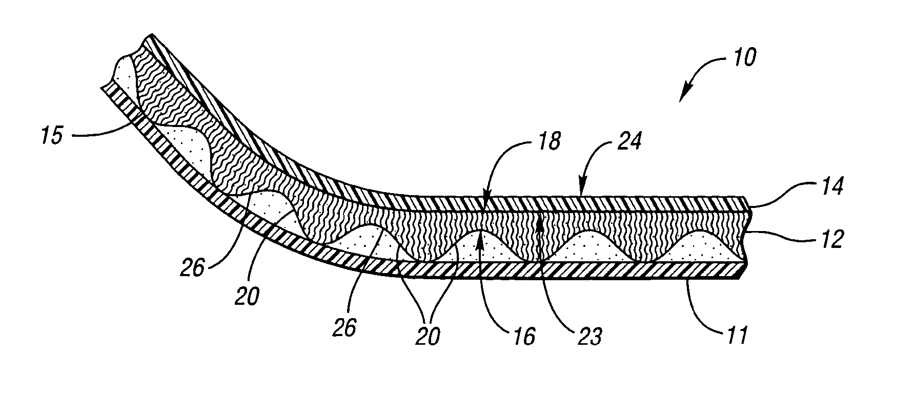
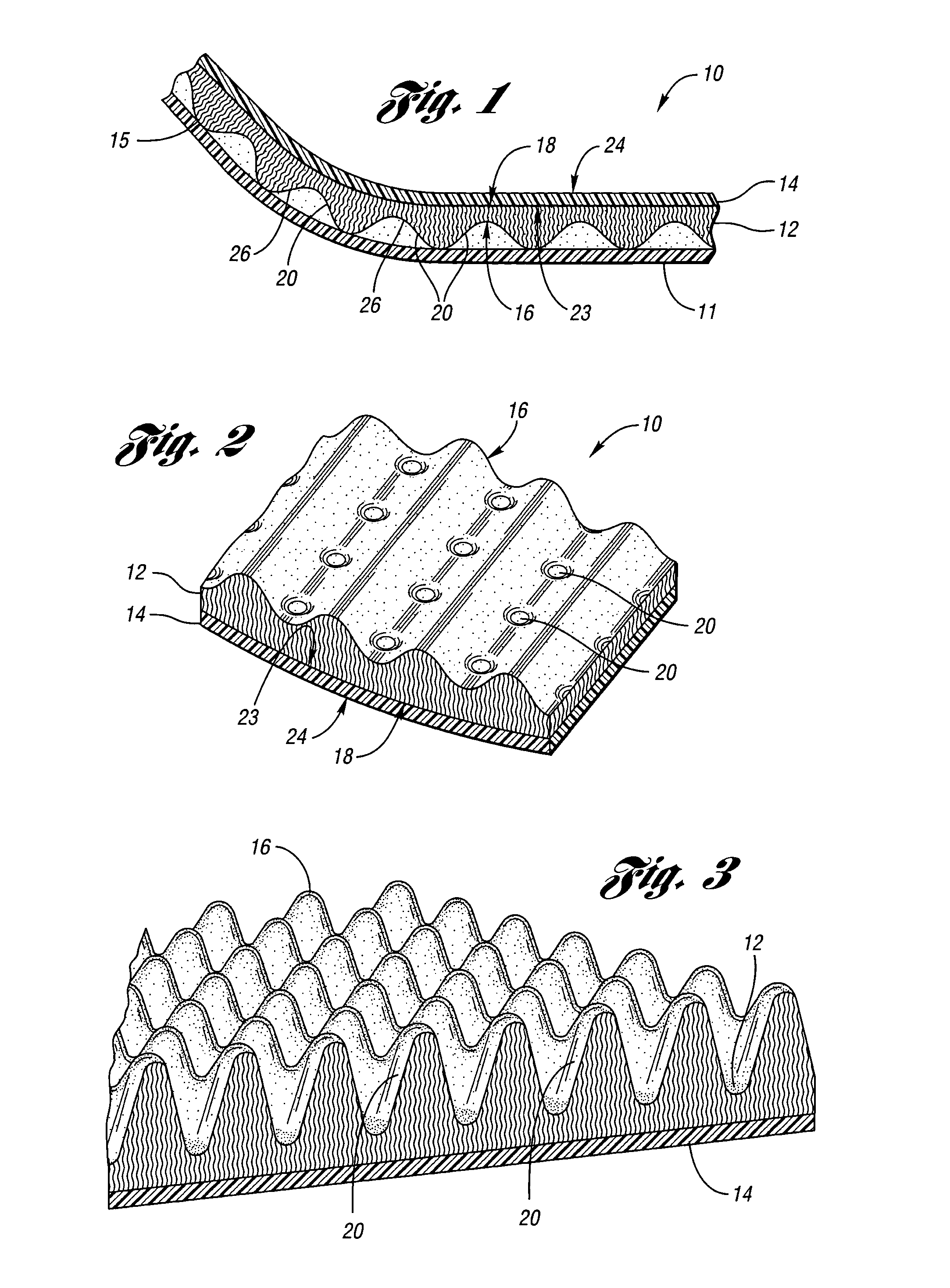
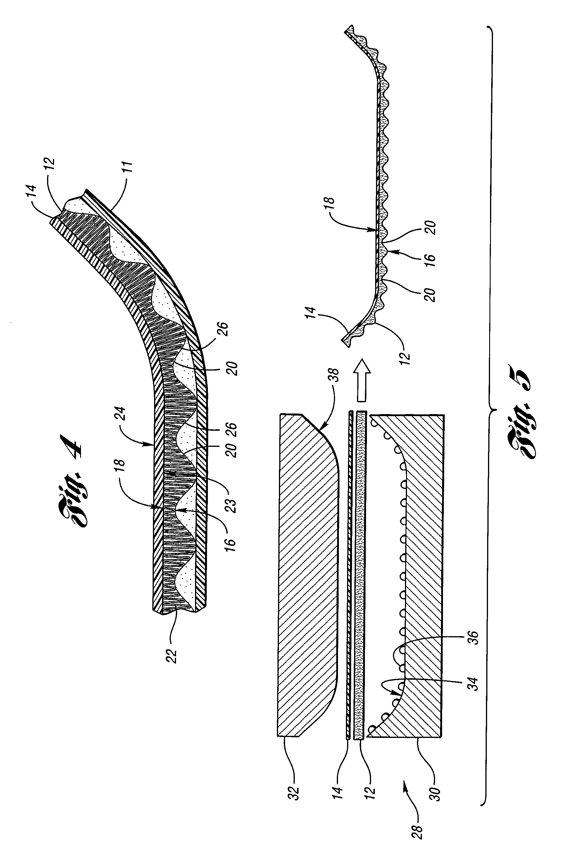
[0014]FIG. 1 illustrates a section of a sound insulation system 10 according to the invention for use within an interior compartment of a vehicle. In the embodiment shown in FIG. 1, for example, the sound insulation system 10 may be configured as a flooring system that is positioned adjacent to a vehicle part 11, such as a floor pan. Alternatively, the sound insulation system 10 may be configured as a headliner, package shelf covering, door panel lining or covering, trunk compartment liner, engine compartment liner, or any other suitable lining or covering system of the vehicle, and the vehicle part 11 may be a vehicle roof, package shelf, door panel, trunk floor, engine compartment wall, or any other suitable part.

[0015] In the embodiment shown in FIGS. 1 and 2, the sound insulation system 10 includes a layer of fibrous padding material, such as fibrous layer 12, and a cover layer 14 attached to the fibrous layer 12. The fibrous layer 12 includes multiple fibers, such as natural f...


PUM

PropertyMeasurementUnit
Fractionaaaaaaaaaa
Frequencyaaaaaaaaaa
Frequencyaaaaaaaaaa

Abstract

A sound insulation system for use with a vehicle includes a layer of fibrous padding material having a first surface and an opposite second surface. The first surface includes multiple spaced apart recesses. The second surface includes a substantially flat surface portion that extends over two adjacent recesses. The multiple recesses are configured to define multiple voids when the sound insulation system is mounted in the vehicle, thereby enhancing acoustical performance of the sound insulation system.

Description


Claims


Application Information

Patent Timeline
Owner INT AUTOMOTIVE COMPONENTS GRP NORTH AMERICA INC
Why Eureka
Try Eureka