Air bag and method for making an air bag

a technology of protective cushions and air bags, which is applied in the direction of pedestrian/occupant safety arrangements, vehicular safety arrangements, vehicle components, etc., can solve the problems of inability to fully cover the cushion, the configuration of inflatable cushions is generally more complex, and the gas leakage is prevalent in discrete areas, so as to achieve the effect of convenient operation

Inactive Publication Date: 2005-01-13
MILLIKEN & CO
View PDF12 Cites 17 Cited by
  • Summary
  • Abstract
  • Description
  • Claims
  • Application Information

AI Technical Summary

Benefits of technology

[0013] An important advantage of the present invention is that it can be adapted for both use in side impact airbags and side curtain airbags. The airbag structure can serve as a side impact airbag directly and as the bottom edge of a side curtain airbag without significant modification of the side curtain panel.
[0014] Still another advantage of the present invention is that the present air bag structure does not require a radical departure from the starting structure for current inflatable tubular structures used for airbags. Rather, it is readily achievable by making a simple series of pinch points in a tube of airbag material. Implementing the present invention, as a result, is simplified and requires no c

Problems solved by technology

Inflatable protective cushions used in passenger vehicles are part of a relatively complex passive restraint system.
However, inflatable cushions for use in the protection of passengers against frontal or side impacts must generally have a more complex configuration since the position of a passenger may not be well-defined and a greater distance may exist between the passenger and the surface of the vehicle agai

Method used


Image

  • Air bag and method for making an air bag
  • Air bag and method for making an air bag
  • Air bag and method for making an air bag

Examples


Embodiment Construction

[0024] Reference will now be made in detail to potentially preferred embodiments and practices. It is, however, to be understood that reference to any such embodiments and practices is in no way intended to limit the invention thereto. On the contrary, it is intended by the applicants to cover all alternatives, modifications and equivalents as may be included within the spirit and scope of the invention as defined by the appended claims

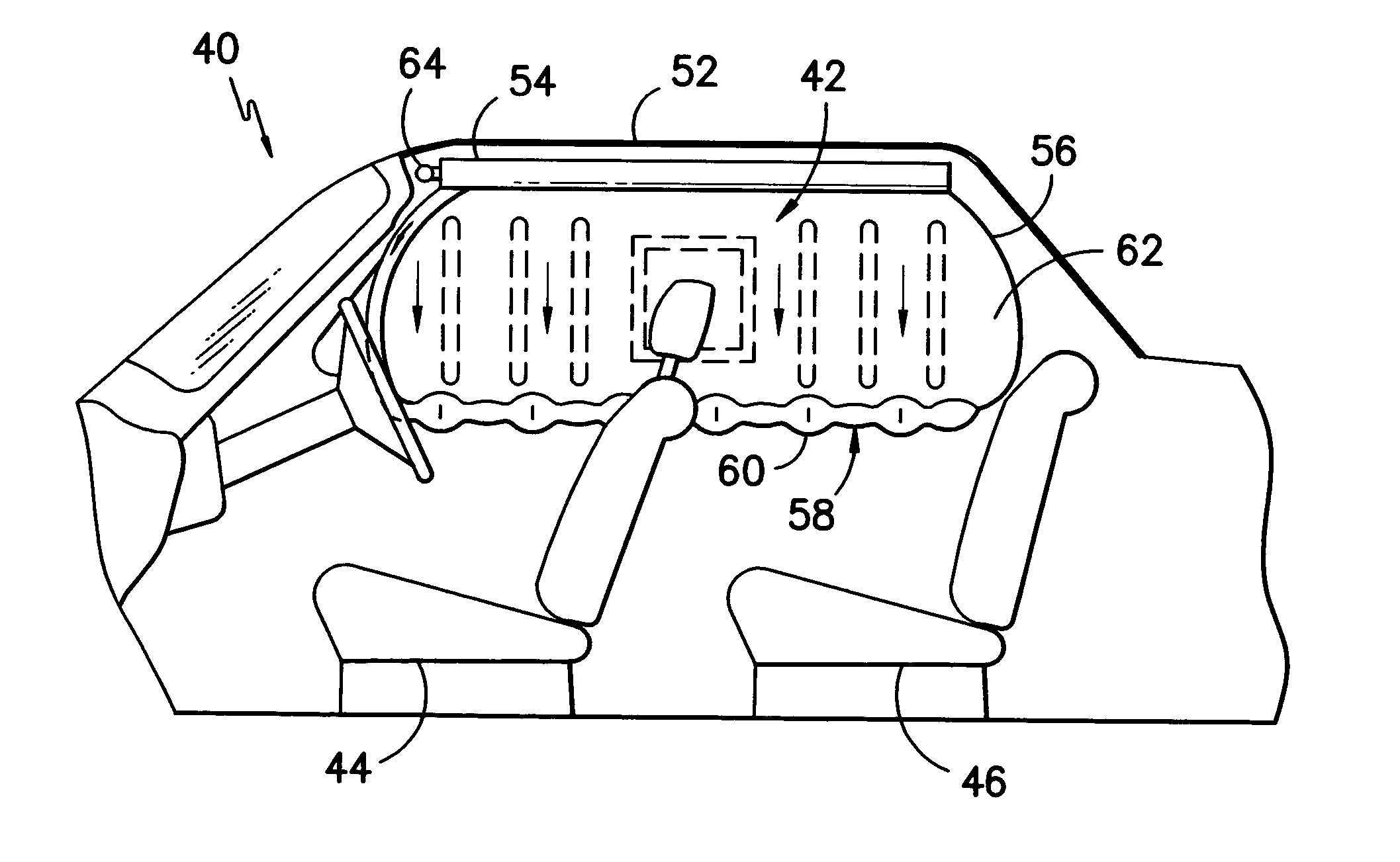
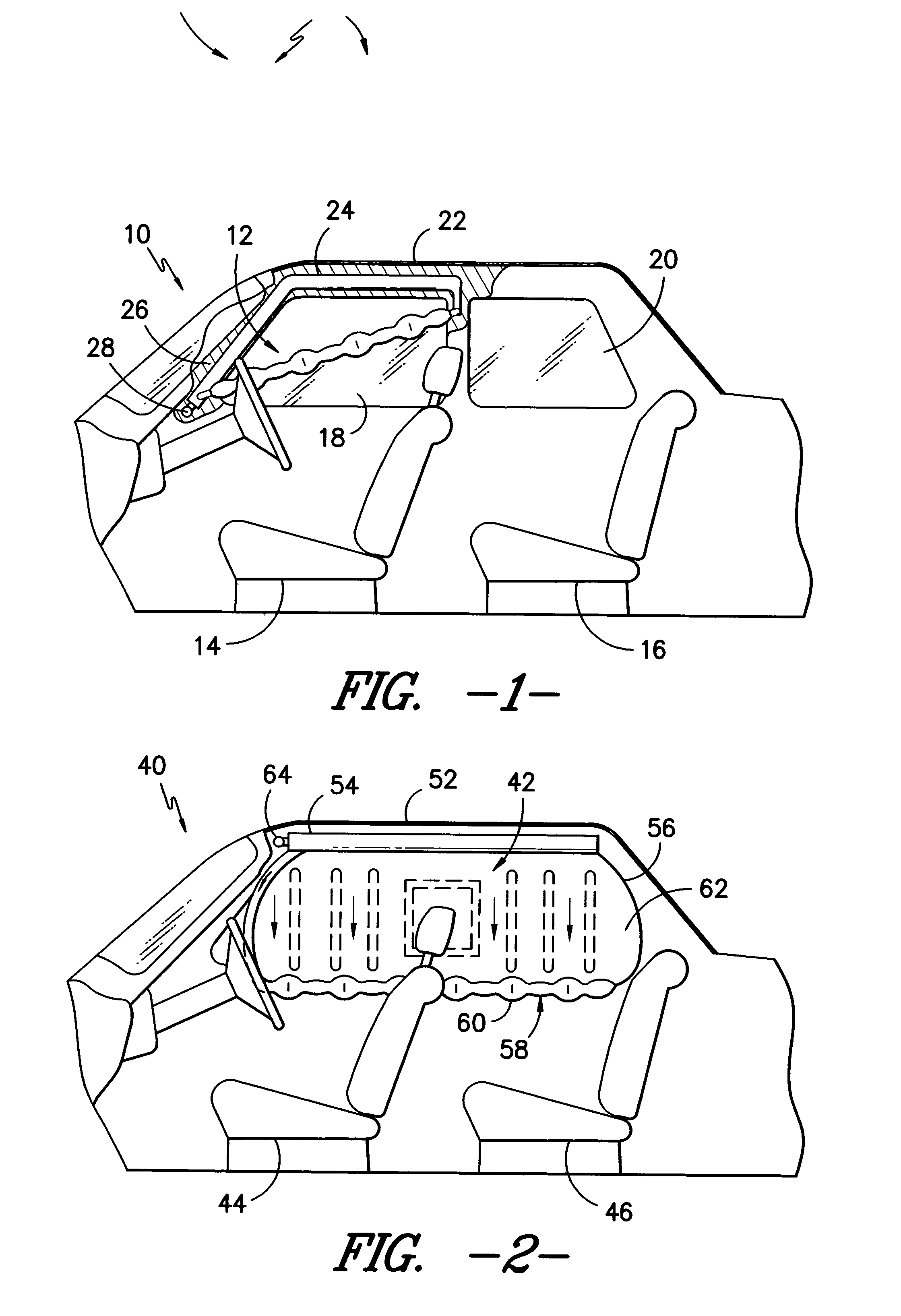
[0025] The term “airbag” will refer generally to a cushion inflated with a gas, whether the gas is air, nitrogen, helium or other inflation medium. The present invention relates to an inflatable airbag structure usable as a side impact airbag or side curtain airbag and characterized by a different shape that generates higher tension on inflation than other inflatable airbag structures, rather than relating to the fabric of airbags, their method of deployment, their enclosure and the method for packing the airbag in the enclosure.

[0026] An embodiment...


PUM


Abstract

An airbag formed to have a series of nodes therein, each node defined by pinching and jointing a portion of alternate opposing sides of a tubular structure so that each node lies generally in a plane at 90° (or near 90°) with respect to an adjacent node. The pinch points or joints are preferably short segments or small areas where the opposing sides are jointed by heat welding, sewing, ultrasonic welding, by adhesives, or by weaving.

Description

BACKGROUND OF THE INVENTION [0001] The present invention relates to inflatable protective cushions, and more specifically relates to cushions formed to contract along a major axis upon inflation. This type of cushion is particularly useful in side protection of occupants in a transportation vehicle, such as an automobile. A process for forming the cushion in an optimum shape according to the present invention is also provided. [0002] Inflatable protective cushions used in passenger vehicles are part of a relatively complex passive restraint system. The main elements of this system are: an impact sensing system, an ignition system, a propellant, an attachment device, a system enclosure, and an inflatable protective cushion. When the impact sensing system senses an impact, the propellant is ignited by the ignition system causing an explosive release of gases that inflate the protective cushion, driving it from the system enclosure to a deployed state proximate to the vehicle occupant ...

Claims


Application Information

Patent Timeline
IPC IPC(8): B60R21/16B60R21/232B60R21/233
CPCB60R21/23184B60R2021/23316B60R21/233B60R21/232
Inventor WANG, YUNZHANG
Owner MILLIKEN & CO
Why Eureka
Try Eureka