This helps you quickly interpret patents by identifying the three key elements:
Problems solved by technology
Method used
Benefits of technology
[0008] An object of the invention is to provide a highly-flexible, reflective display which can be manufactured easily, consumes little (or no in the case of bistable displays) power, and can, therefore, be incorporated into a variety of
Problems solved by technology
To date, widespread incorporation of displays has been hindered because such applications generally require flexible displays that consume very little power.
Despite much effort directed to developing highly-flexible, reflective display media, there are relatively few examples of displays formed on semi-flexible substrates, and these examples have found only moderate success.
Nevertheless, problems remain with liquid crystal alignment in TN and STN displays, cholesteric displays are sensitive to changes in their cell gap, and local stress can cause changes in the
Method used
Image
Click on the blue label to locate the original text in one second.
Reading with bidirectional positioning of images and text.
Examples
Example
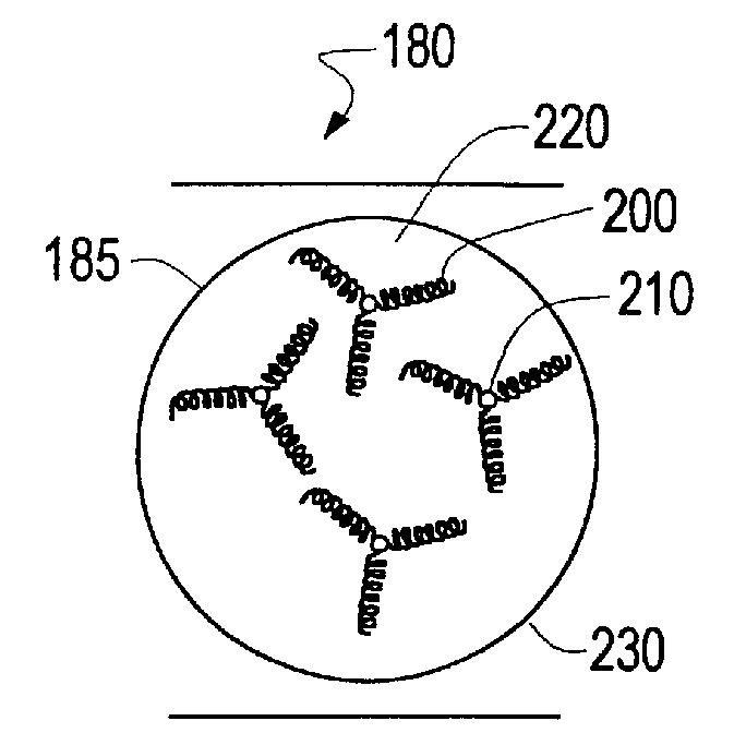
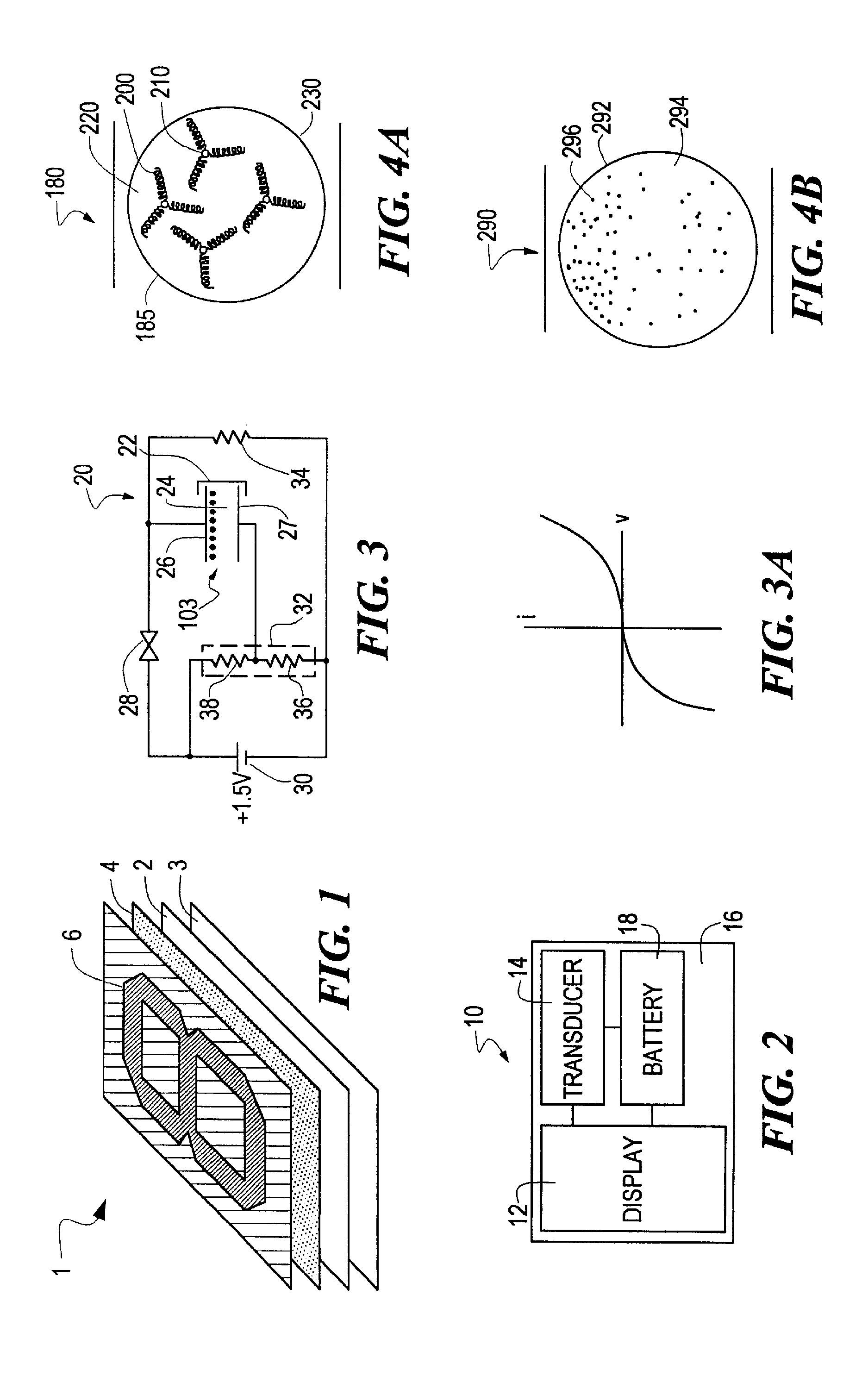
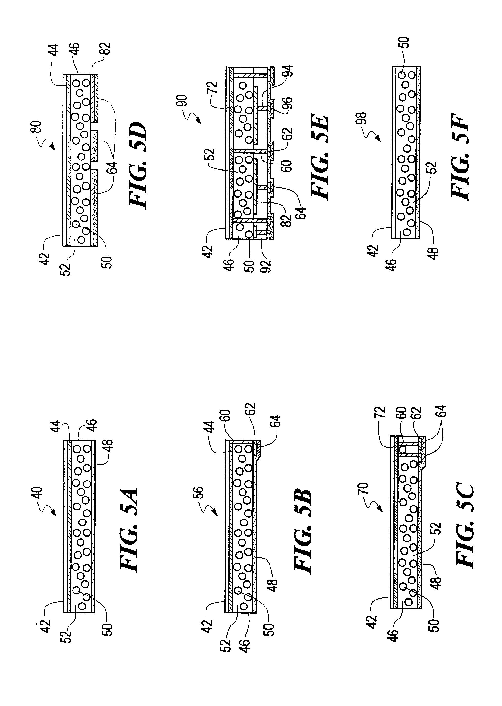
[0036] According to the present invention, a substrate is provided and an electronic ink is printed onto a first area of the substrate. The present invention takes advantage of the physical properties of an electronic ink which permits a wide range of printing and coating techniques to be used in creating a display. An electronic ink is an optoelectronically active material which comprises at least two phases: an electrophoretic contrast media phase and a coating / binding phase. The electrophoretic phase comprises, in some embodiments, a single species of electrophoretic particles dispersed in a clear or dyed medium, or more than one species of electrophoretic particles having distinct physical and electrical characteristics dispersed in a clear or dyed medium. The coating / binding phase includes, in one embodiment, a polymer matrix that surrounds the electrophoretic phase. In this embodiment, the polymer in the polymeric binder is capable of being dried, crosslinked, or otherwise cur...
PUM
Property
Measurement
Unit
Electrical conductor
aaaaa
aaaaa
Electrophoretic
aaaaa
aaaaa
Abstract
A process for creating an electronically addressable display includes multiple printing operations, similar to a multi-color process in conventional screen printing. In some of the process steps, electrically non-active inks are printed onto areas of the receiving substrate, and in other steps, electrically active inks are printed onto different areas of the substrate. The printed display can be used in a variety of applications. This display can be used as an indicator by changing state of the display after a certain time has elapsed, or when a certain pressure, thermal, radiative, moisture, acoustic, inclination, pH, or other threshold is passed. In one embodiment, the display is incorporated into a battery indicator. A sticker display is described. The sticker is adhesive backed and may then be applied to a surface to create a functional information display unit. This invention also features a display that is both powered and controlled using radio frequencies. It describes a complete system for controlling, addressing, and powering a display. The system includes an antenna or antennae, passive charging circuitry, and active control system, a display, and an energy storage unit. There is also a separate transmitter that provides the remote power for the display. The system is meant to be used anywhere it is useful to provide intermittent updates of information such as in a store, on a highway, or in an airport. A tile-based display allowing a modular system for large area display is created using a printable display material.
Description
CROSS-REFERENCE TO RELATED APPLICATIONS [0001] This application is a continuation of application Ser. No. 09 / 141,126, filed Aug. 27, 1998. [0002] The aforementioned application Ser. No. 09 / 141,126 claims priority to U.S. Ser. No. 60 / 057,133 filed Aug. 28, 1997, U.S. Ser. No. 60 / 057,716, filed Aug. 28, 1997, U.S. Ser. No. 60 / 057,122, filed Aug. 28, 1997, U.S. Ser. No. 60 / 057,798, filed Aug. 28, 1997, U.S. Ser. No. 60 / 057,799 filed Aug. 28, 1997, U.S. Ser. No. 60 / 057,163 filed Aug. 28, 1997, U.S. Ser. No. 60 / 057,118, filed Aug. 28, 1997, U.S. Ser. No. 60 / 059,358, filed Sep. 19, 1997, U.S. Ser. No. 60 / 065,630 filed Nov. 18, 1997, U.S. Ser. No. 60 / 065,605 filed Nov. 18, 1997, U.S. Ser. No. 60 / 066,147, filed Nov. 19, 1997, U.S. Ser. No. 60 / 066,245, filed Nov. 20, 1997, U.S. Ser. No. 60 / 066,246, filed Nov. 20, 1997, U.S. Ser. No. 60 / 066,115 filed Nov. 21, 1997, U.S. Ser. No. 60 / 066,334 filed Nov. 21, 1997, U.S. Ser. No. 60 / 066,418 filed Nov. 24, 1997, U.S. Ser. No. 60 / 070,940 filed Jan. 9...
Claims
Application Information
Patent Timeline
Application Date:The date an application was filed.
Publication Date:The date a patent or application was officially published.
First Publication Date:The earliest publication date of a patent with the same application number.
Issue Date:Publication date of the patent grant document.
PCT Entry Date:The Entry date of PCT National Phase.
Estimated Expiry Date:The statutory expiry date of a patent right according to the Patent Law, and it is the longest term of protection that the patent right can achieve without the termination of the patent right due to other reasons(Term extension factor has been taken into account ).
Invalid Date:Actual expiry date is based on effective date or publication date of legal transaction data of invalid patent.