

Method and device for preventing dew condensation and frosting on optical glass window
a technology of optical glass and frosting, which is applied in the direction of television systems, instruments, process and machine control, etc., can solve the problems of deforming an image received, consuming more energy for heating the entire camera, and risking the maintenance of the vacuum state, so as to/or ice, and prevent the formation of dew
- Summary
- Abstract
- Description
- Claims
- Application Information
AI Technical Summary
Benefits of technology
Problems solved by technology
Method used
Image

Examples
first embodiment
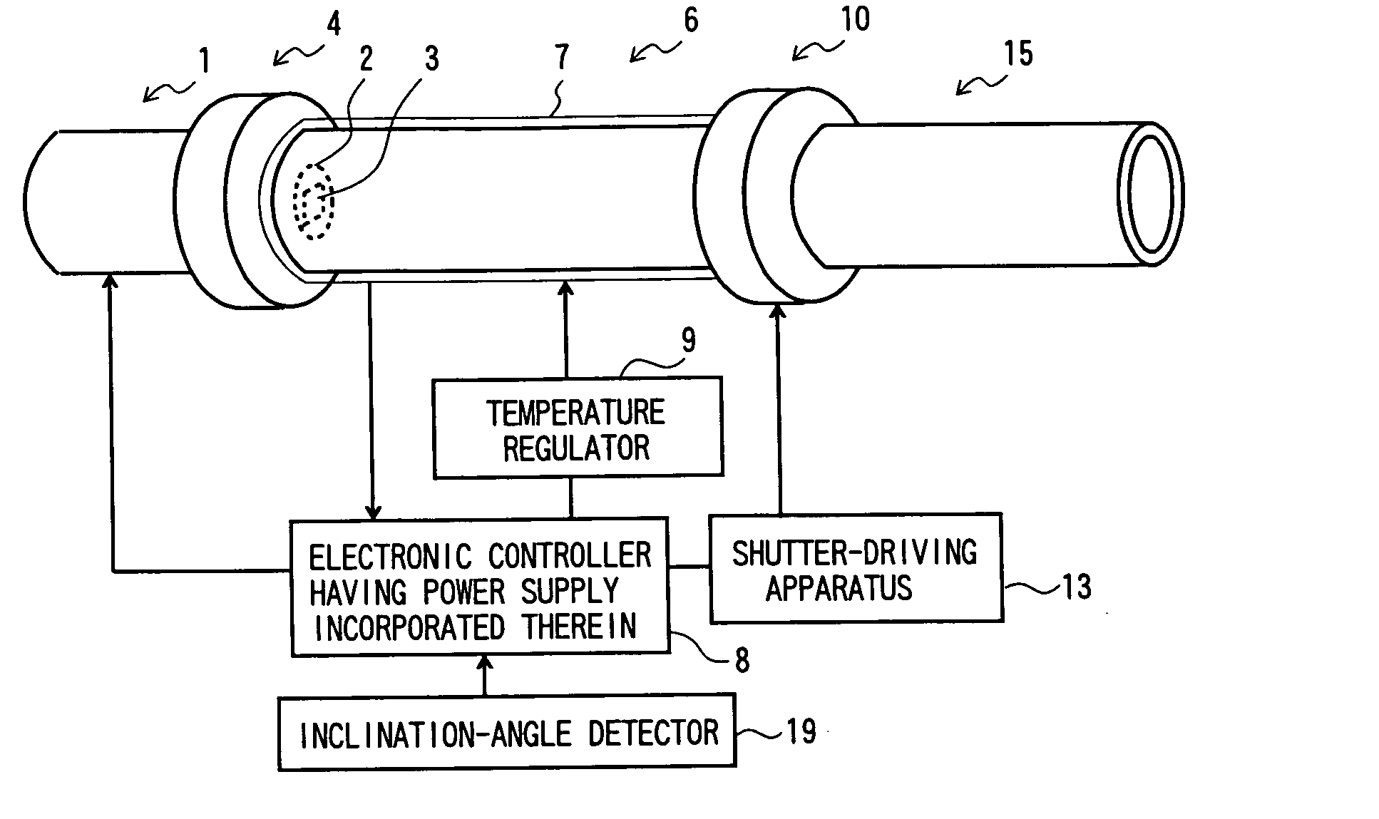
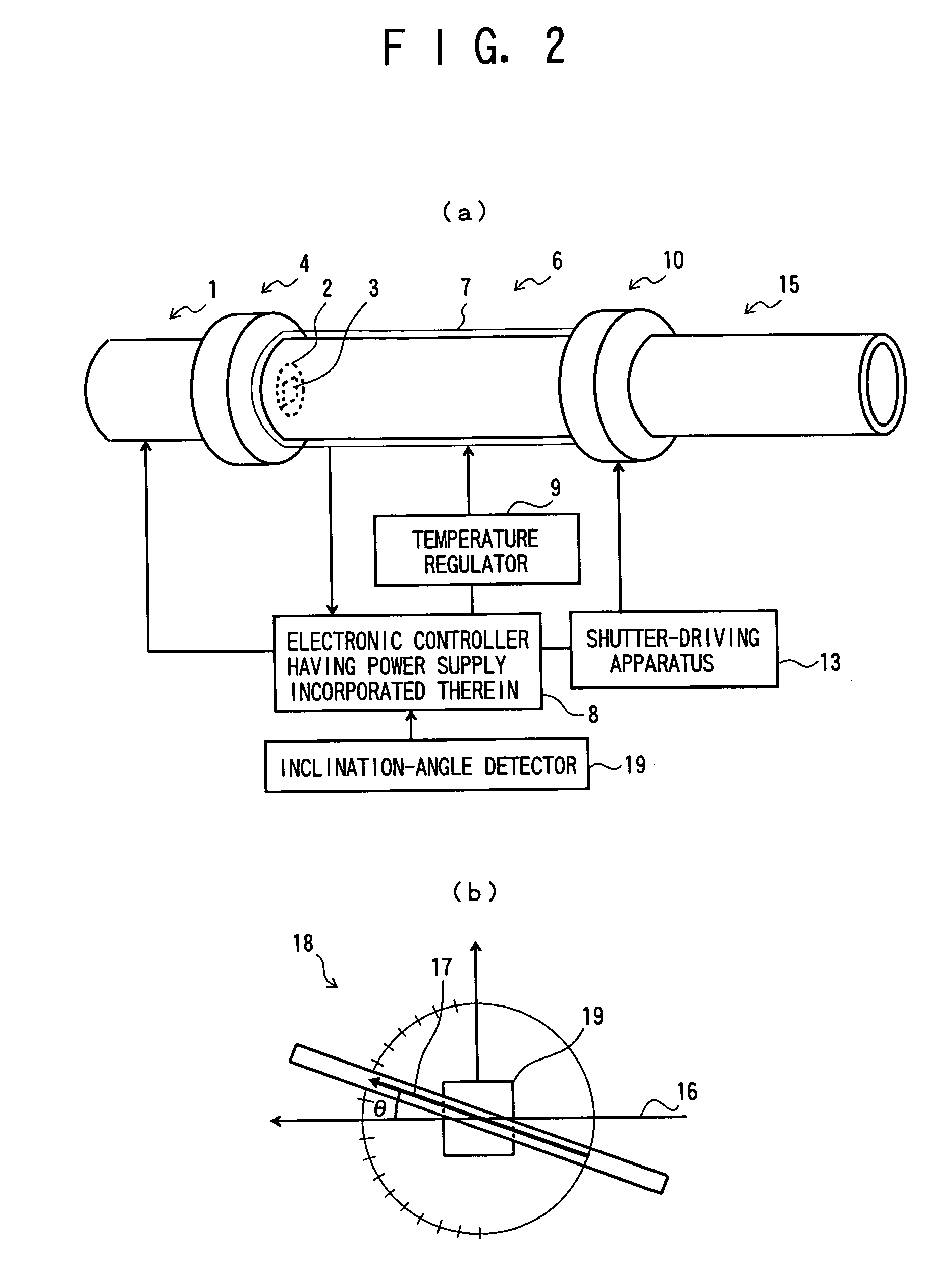
[0029]FIG. 2 is a schematic view of an apparatus for preventing formation of dew and / or ice on an optical glass window, according to the present invention, wherein FIG. 2(a) is an external perspective view of the apparatus for preventing formation of dew and / or ice on an optical glass window, and FIG. 2(b) is a schematic view of an inclination-angle detector of the apparatus for preventing formation of dew and / or ice on an optical glass window. Also, FIG. 3 is a sectional view of the apparatus for preventing formation of dew and / or ice on an optical glass window.
[0030] In these drawings, with respect to reference numbers 1 to 15A, 1 represents a CCD camera, 2 represents a glass window, 3 represents a CCD enclosed inside the glass window 2, 1A represents a flange portion of the CCD camera 1, 4 represents a first joint portion, 5 represents an insulating member, 6 represents a protective tube, 6A represents a first flange portion of the protective tube 6, 6B represents a second flange...
second embodiment
[0036]FIG. 4 is an external perspective view of an apparatus for preventing formation of dew and / or ice on an optical glass window, according to the present invention, and FIG. 5 is a sectional view of the apparatus for preventing formation of dew and / or ice on an optical glass window.
[0037] In these figures, with respect to reference numbers 21 to 28, 21 represents a camera portion, 22 represents a lens portion connected to the camera portion 21, 22A represents a flange of the lens portion 22, 23 represents a glass window of the lens portion 22, 24 represents a lens, 25 represents a joint portion, 26 represents an insulating member, 27 represents a protective tube, 27A represents a flange of the protective tube, and 28 represents a small opening in the front portion of the protective tube 27.
[0038] In this embodiment, the lens portion 22 is connected to the camera portion 21, the lens 24 facing the glass window 23 is disposed in the lens portion 22, and the joint portion 25 is mad...
PUM
 Abstract
Description
Claims
Application Information