Electric actuator

a technology of electric actuators and actuators, which is applied in the direction of linear bearings, mechanical devices, gearing, etc., can solve the problems of becoming difficult to secure the rigidity of electric actuators, and achieve the effect of reducing the number of parts and lightening the weigh

Inactive Publication Date: 2005-01-20
SMC CORP
View PDF7 Cites 49 Cited by
  • Summary
  • Abstract
  • Description
  • Claims
  • Application Information

AI Technical Summary

Benefits of technology

[0008] A general object of the present invention is to provide an electric actuator which makes it possible to reduce the number of parts and lighten the weight without the need for a frame.

Problems solved by technology

If, however, the frame 2 is removed from the electric actuator 1 to reduce the number of parts and to lighten the weight, it will become difficult to secure the rigidity of the electric actuator 1.

Method used


Image

  • Electric actuator
  • Electric actuator
  • Electric actuator

Examples


Embodiment Construction

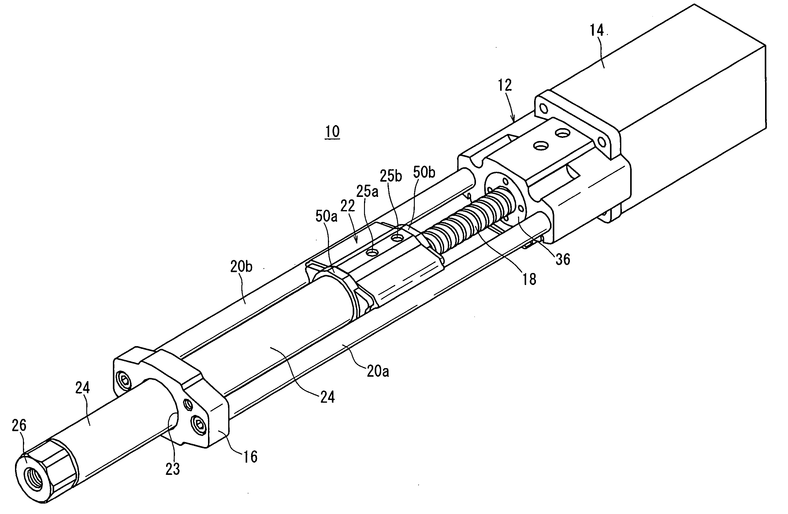
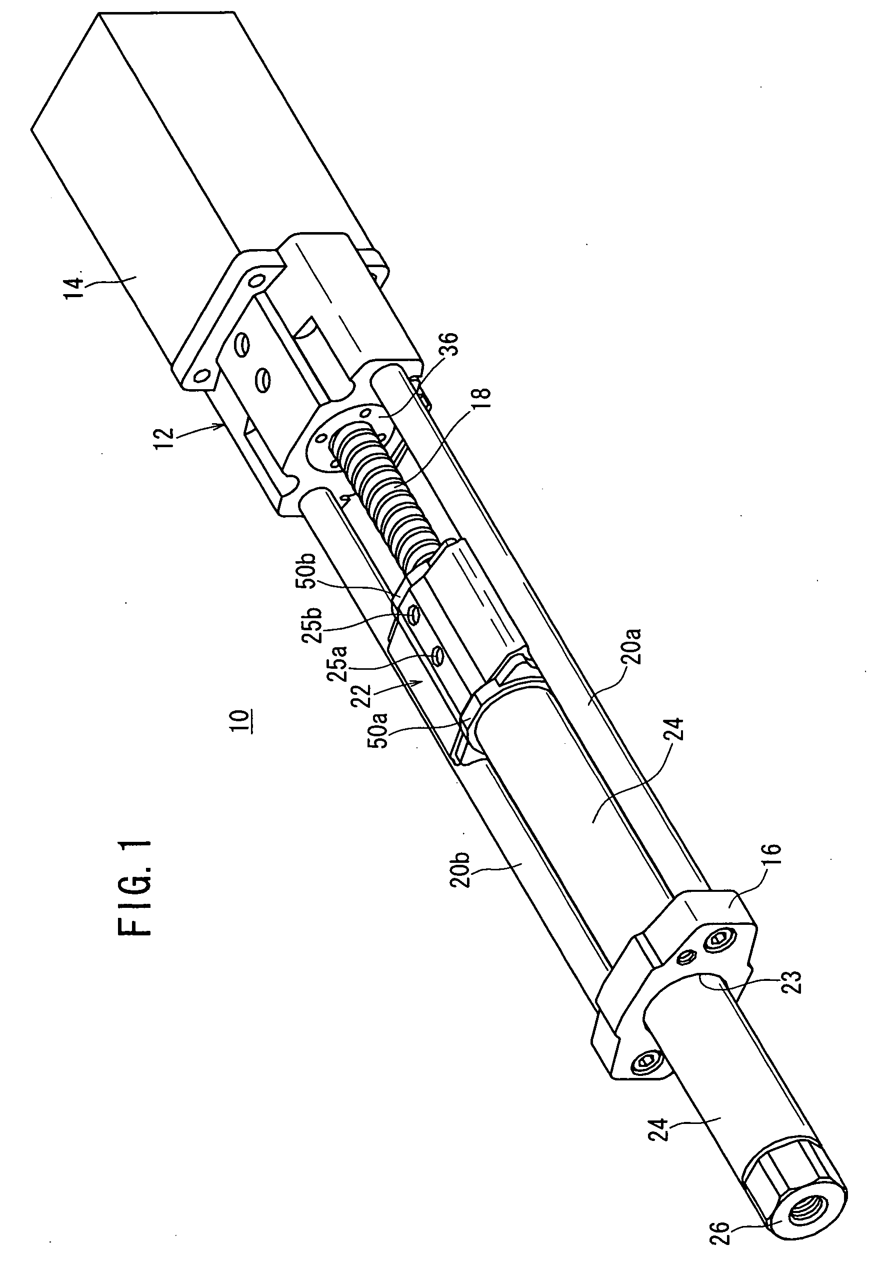
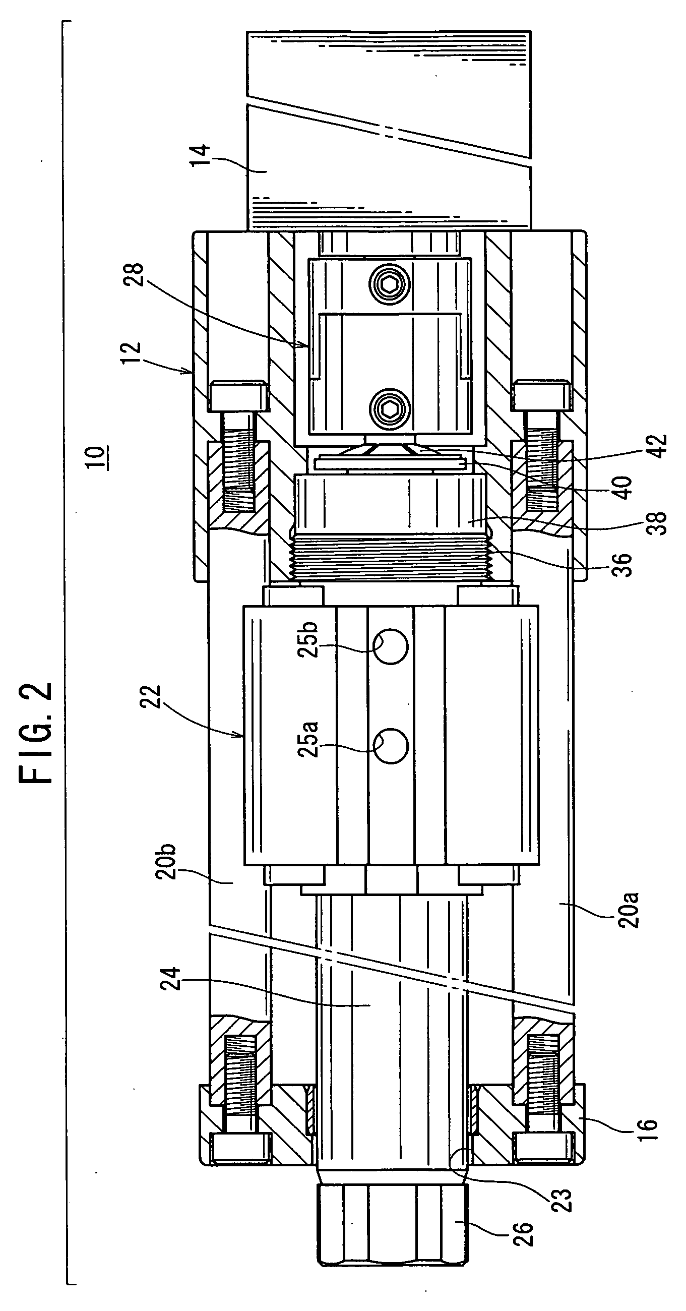
[0031] With reference to FIGS. 1 to 3, reference numeral 10 indicates an electric actuator according to an embodiment of the present invention.

[0032] The electric actuator 10 comprises a housing 12 having a substantially flat block member, a rotary driving source 14 which is connected to one end of the housing 12, a rod cover (end block) 16 which is separated from the housing 12 at a predetermined distance, and which is disposed on the opposite side of the rotary driving source 14, and a feed screw shaft (driving force-transmitting shaft) 18 which transmits the rotary driving force of the rotary driving source 14 via a coupling member.

[0033] The electric actuator 10 further comprises a pair of guide rods 20a, 20b, a piston 22, a hollow cylindrical piston rod 24, and a socket 26. The guide rods 20a, 20b are arranged in parallel to one another with the feed screw shaft 18 disposed in-between. Each of the guide rods 20a, 20b has one end connected to the housing 12 and the other end c...


PUM


Abstract

An electric actuator comprises a feed screw shaft which allows a piston and a piston rod to make rectilinear reciprocating motion by converting the rotary driving force of a rotary driving source into rectilinear motion to transmit to the piston and the piston rod, a rod cover which separated from a housing at a predetermined distance in the axial direction, and a pair of guide rods each of which has one end connected to the rod cover and the other end connected to the housing and which are parallel to one another with the piston intervening therebetween to guide the piston.

Description

BACKGROUND OF THE INVENTION [0001] 1. Field of the Invention [0002] The present invention relates to an electric actuator capable of making rectilinear reciprocating motion of a displaceable member under a rotary driving action of a rotary driving source. [0003] 2. Description of the Related Art [0004] A transport mechanism such as an actuator has been conventionally used, for example, in order to transport a workpiece. [0005] A conventional electric actuator is shown in FIGS. 20 and 21 (see, for example, Japanese Laid-Open Patent Publication No. 11-30234). [0006] The conventional electric actuator 1 includes a slider 4 which is displaceable along a recess 3 of a frame 2, and a screw shaft 6 which is driven by an unillustrated motor and which is screwed to a nut member 5 that is detachable with respect to the slider 4. Screw shaft support members 7a, 7b, which rotatably support the screw shaft 6, are provided at both ends of the screw shaft 6. The screw shaft support members 7a, 7b ...

Claims


Application Information

Patent Timeline
Patent Type & Authority Applications(United States)
IPC IPC(8): F16C29/06F16H25/20
CPCF16H25/20F16H25/2204Y10T74/18648F16H2025/204F16H2025/2075F16H2025/2034F16C29/06
Inventor NAGAI, SHIGEKAZUMASUI, RYUICHIMIYAHARA, MASAKI
Owner SMC CORP
Why Eureka
Try Eureka