
Network restoration

a network restoration and network technology, applied in the field of telecommunications, can solve the problems of deleting the failed path and ending the temporary protection, and achieve the effect of no performance differen

Active Publication Date: 2005-01-20
RPX CORP
View PDF12 Cites 57 Cited by
  • Summary
  • Abstract
  • Description
  • Claims
  • Application Information

AI Technical Summary

Benefits of technology

The present invention provides an improved method for restoring network traffic in case of failure. The method involves establishing a temporary 1+1 path protection involving the failed path and an alternate restoration path. Traffic is duplicated at the first and second termination nodes and the second node switches to receive traffic over the alternate path but continues to monitor the failed path. If the failure condition persists, the method may cease the temporary protection and delete the failed path. The invention allows for both reversible and non-reversible restoration, and works even in the case of two unidirectional failures. The method is performed in about the same time as traditional restoration without temporary protection circuit.

Problems solved by technology

If after a predetermined period of time, the failure still persists, the method may cease the temporary protection and delete the failed path.

Method used


Image

  • Network restoration
  • Network restoration

Examples


Embodiment Construction

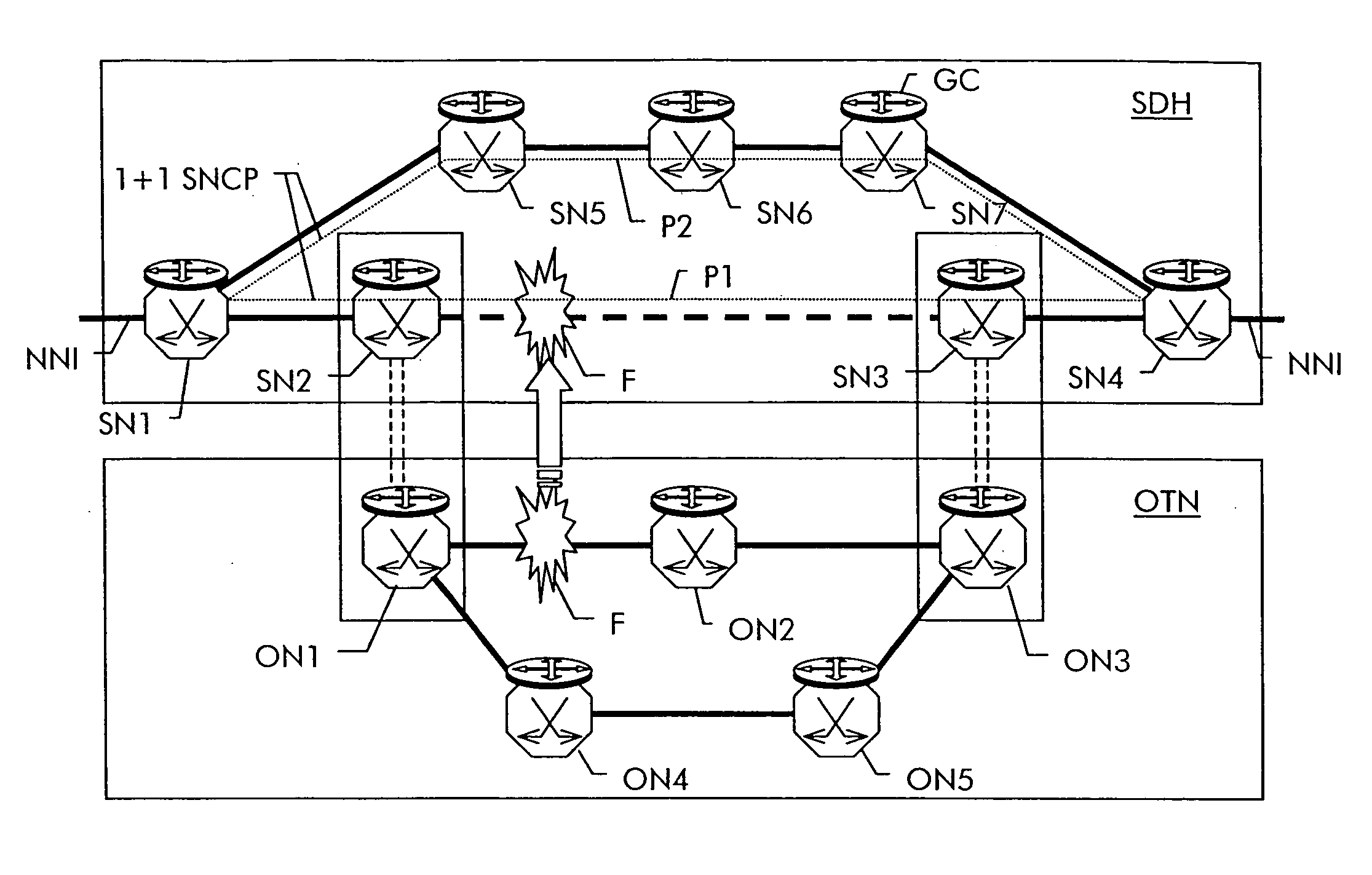
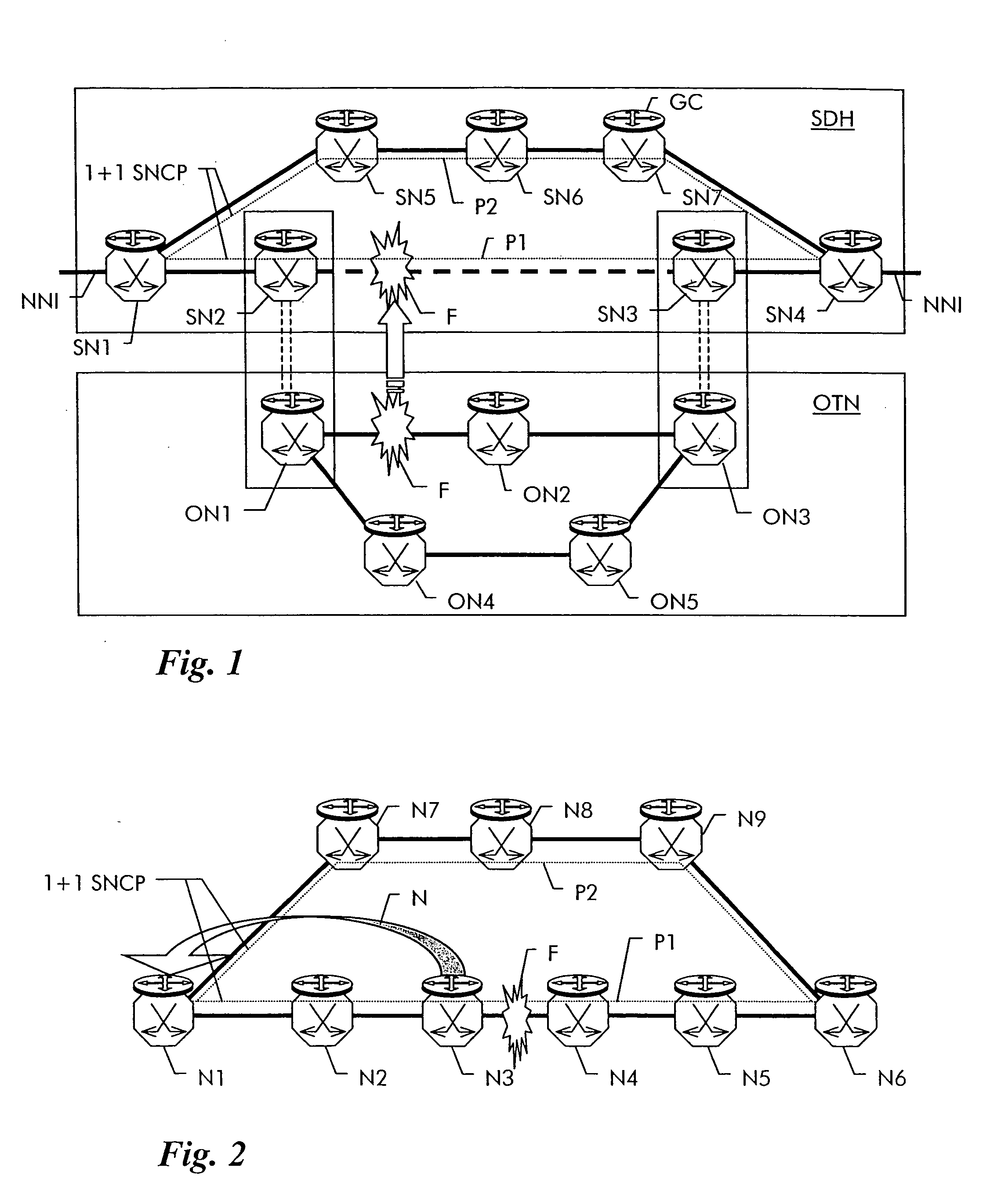
[0022]FIG. 1 shows by way of a non-limiting example a layered transport network which contains a first lower layer network OTN composed of network elements ON1 to ON5 and a second higher layer network SDH composed of network elements SN1 to SN7. The lower layer network is an optical transport network OTN as defined in ITU-T G.709. ON1 is physically connected to ON2 and to ON4, ON2 is connected to ON3 and ON5 is connected to ON4 and to ON3. The interconnections are optical fibers and carry wavelength multiplexed signals, where each wavelength represents a multiplex unit in the OTN.

[0023] The higher layer network is an SDH network as defined in ITU-T G.707. SN1 is connected to SN2 and to SN5, SN6 is connected to SN5 and SN7 and SN4 is conencted to SN3 and SN7. Between SN2 and SN3 exists a connection which uses a wavelength channel through the underlying OTN from ON1 over ON2 to ON3. In the OTN, a path exists thus for the SDH client layer between ON1 and ON3 across ON2.

[0024] Both ne...


PUM


Abstract

A method of restoring an active path between two nodes of a transport network upon occurrence of a failure includes the steps of determining an alternate path through the network and establishing a path protection involving the failed active path and the alternate path. If in layered networks, a failed path is restored at a lower layer and at a higher layer concurrently, the restoration actions in the higher network layer can thus be reverted easily.

Description

[0001] The invention is based on a priority application EP 03291785.8 which is hereby incorporated by reference. FIELD OF THE INVENTION [0002] The present invention relates to the field of telecommunications and more particularly to a method and related network management system for restoring a path through a transport network upon occurrence of a failure. BACKGROUND OF THE INVENTION [0003] Transport networks serve for the physical layer transport of high bitrate tributary signals. In particular, the signals transmitted over a transport network are encoded and multiplexed into a continuous bit stream structured into frames of the same length. Within this constant bitrate bit stream, the frames are repeated periodically with a frame repetition rate of typically 8 kHz and are substructured according to a multiplexing hierarchy. An example of such a multiplexing hierarchy is SDH (Synchronous Digital Hierarchy, see ITU-T G.707 October 2000) where the frames are termed synchronous transp...

Claims


Application Information

Patent Timeline
Patent Type & Authority Applications(United States)
IPC IPC(8): H04J3/08H04L45/24H04L45/28
CPCH04J3/085H04L41/0663H04L45/60H04L45/22H04L45/28H04L41/12
Inventor BELLER, DIETERJAKEL, HANS-JORG
Owner RPX CORP
Learn More