
Frame assembly for external fixation device and associated method

Active Publication Date: 2005-01-20
BIOMET MFG CORP
View PDF15 Cites 44 Cited by
  • Summary
  • Abstract
  • Description
  • Claims
  • Application Information

AI Technical Summary

Benefits of technology

[0009] An advantage of the present invention is the provision of a method and apparatus for the external fixation of bone which allows the rate of angular, rotational and / or translational correction of bone deformities and malunions to be easily and more accurately controlled.
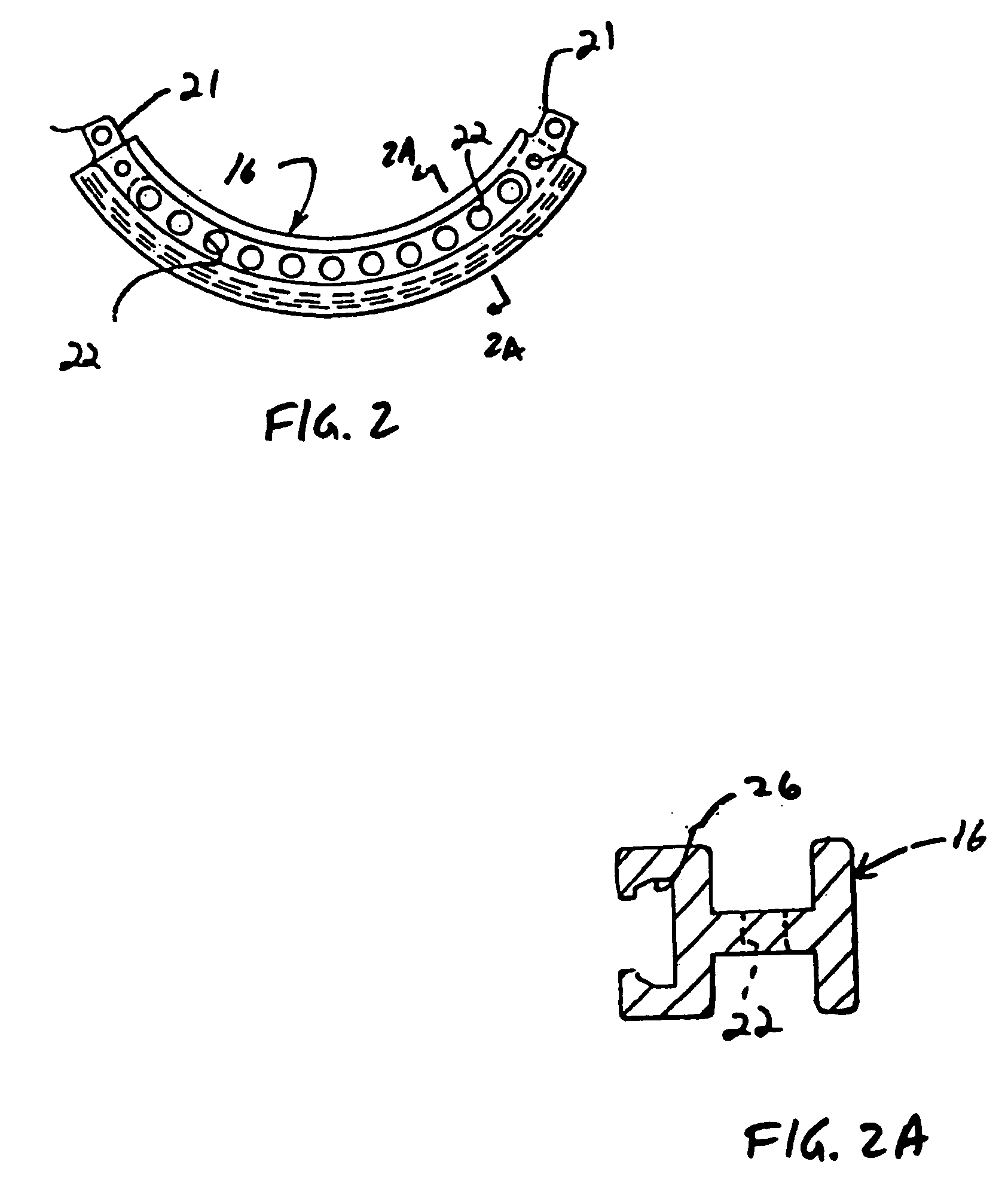
[0010] In one particular form, the present invention provides a frame assembly for an external fixation device. The frame assembly includes a first arc segment and a second arc segment. The first arc segment is for interconnection to a first bone portion. The second arc segment is for interconnection to a second bone portion. The first arc segment is coupled to the second arc segment for controlled relative rotation.
[0011] In another particular form, the present invention provides an articulating module for an external fixation device. The articulating module includes a central member, a first pivot segment and a second pivot segment. The first pivot segment is coupled to the central member for driven rotation about a first pivot axis. The second pivot segment is coupled to the central member for driven rotation about a second pivot axis. The second pivot axis is substantially perpendicular to the first pivot axis.
[0012] In yet another particular form, the present invention provides a method of correcting a rotational deformity or malunion of a bone having a longitudinal axis. The method includes the step of providing an external fixation device including a frame assembly with a first arc segment coupled to a second arc segment. The method additionally includes the steps of interconnecting the first arc segment to a first bone portion and interconnecting the second arc segment to a second bone portion. The method further includes the step of rotating the first arc segment relative to the second arc segment to correct the rotational deformity or malunion of the bone.

Problems solved by technology

For example, the need for establishing such a secured relationship is often a result of a fracture which has occurred to the bone.
The need for making such an adjustment is frequently the result of bone deformity.
Such bone deformities may result from congenital defects including but not limited to Blount's Disease, Tibia Vara, and Hypophosphatemic Rickets.

Method used


Image

  • Frame assembly for external fixation device and associated method
  • Frame assembly for external fixation device and associated method
  • Frame assembly for external fixation device and associated method

Examples


Embodiment Construction

[0036] The following description of the preferred embodiment(s) is merely exemplary in nature and is in no way intended to limit the invention, its application, or uses.

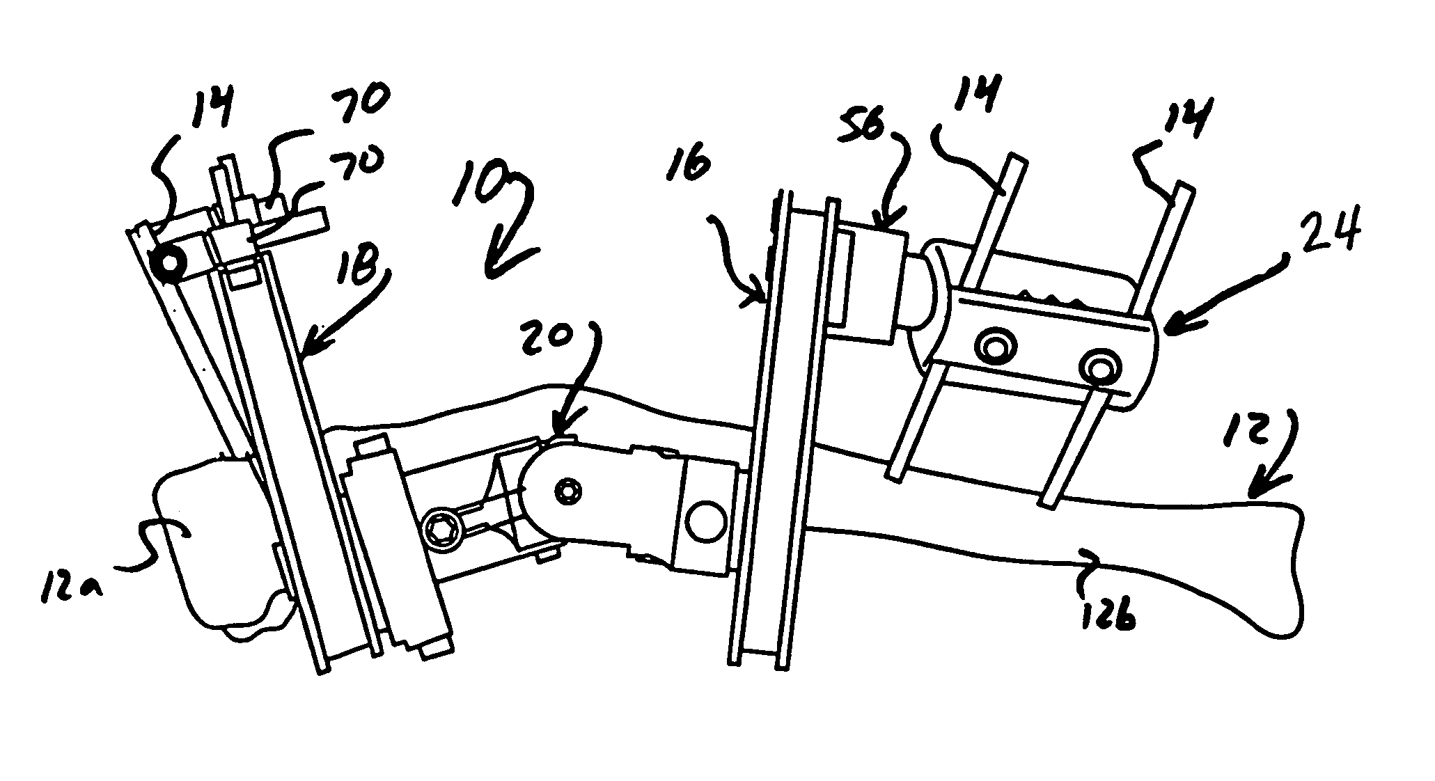
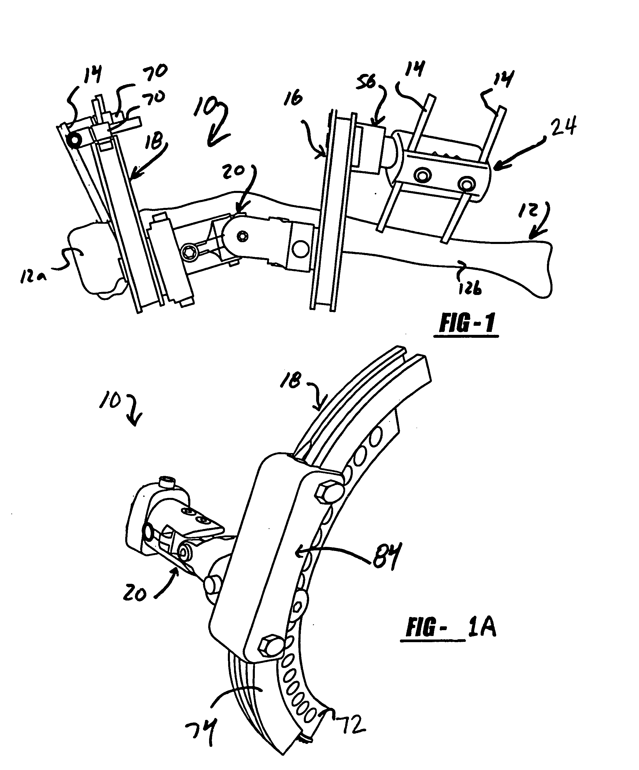
[0037] With general reference to FIGS. 1 through 17 of the drawings, an apparatus for the external fixation and correction of a bone constructed in accordance with the teachings of a preferred embodiment of the present invention is illustrated and generally identified at reference character 10. With particular reference to the environmental view of FIG. 1, the apparatus 10 is shown connected to a bone 12 through a plurality of bone screws 14 which serve to secure a first bone portion 12a relative to a second bone portion 12b.

[0038] In the exemplary application illustrated, the first and second bone portions 12a and 12b secured by the apparatus 10 are of a single bone 12. The bone 12 shown in the drawings represents a human tibia. It is to be understood, however, that the apparatus 10 may be operatively attached to ...


PUM


Abstract

Frame assembly for external fixation device and associated method. The frame assembly includes a first arc segment and a second arc segment. The first arc segment is for interconnection to a first bone portion. The second arc segment is for interconnection to a second bone portion. The first arc segment is coupled to the second arc segment for controlled relative rotation.

Description

CROSS-REFERENCE TO RELATED APPLICATION [0001] This application claims is a continuation of U.S. patent application Ser. No. 10 / 619,536, filed Jul. 15, 2003, and claims the benefit of U.S. Provisional Patent Application No. 60 / 395,814, filed Jul. 15, 2002.FIELD OF THE INVENTION [0002] The present invention relates to the external fixation of bones during orthopedic surgical applications, such as the repair of bone fractures and the correction of bone defects. More particularly, the present invention relates to a method and apparatus which allow for gradual and controlled correction of bone deformities and malunions. The various applications of the present invention involve gradual angular, translational and rotational correction of bone deformities and malunions. BACKGROUND OF THE INVENTION [0003] In various orthopedic surgical procedures, it is necessary to secure two bone portions in a relatively fixed relationship to each other. For example, the need for establishing such a secure...

Claims


Application Information

Patent Timeline
IPC IPC(8): A61B17/64A61B17/66
CPCA61B17/66A61B17/6416
Inventor WALULIK, STEPHEN B.BAILEY, KIRK J.LEUNG, TAKKWONG ROSS
Owner BIOMET MFG CORP
Learn More