Head restraint device with back member

a head restraint and back member technology, applied in the direction of respiratory device storage, transportation and packaging, protective clothing, etc., can solve the problem that the driver may easily egress into and out of the vehicl

Inactive Publication Date: 2005-01-27
SAFETY DYNAMICS
View PDF5 Cites 19 Cited by
  • Summary
  • Abstract
  • Description
  • Claims
  • Application Information

AI Technical Summary

Benefits of technology

[0028] A further object of the invention is to provide a device that is not bulky.

Problems solved by technology

Moreover, as the device is carried on the driver, and is not attached to any component of the vehicle, the driver may easily egress into and out of the vehicle.

Method used


Image

  • Head restraint device with back member
  • Head restraint device with back member

Examples


Embodiment Construction

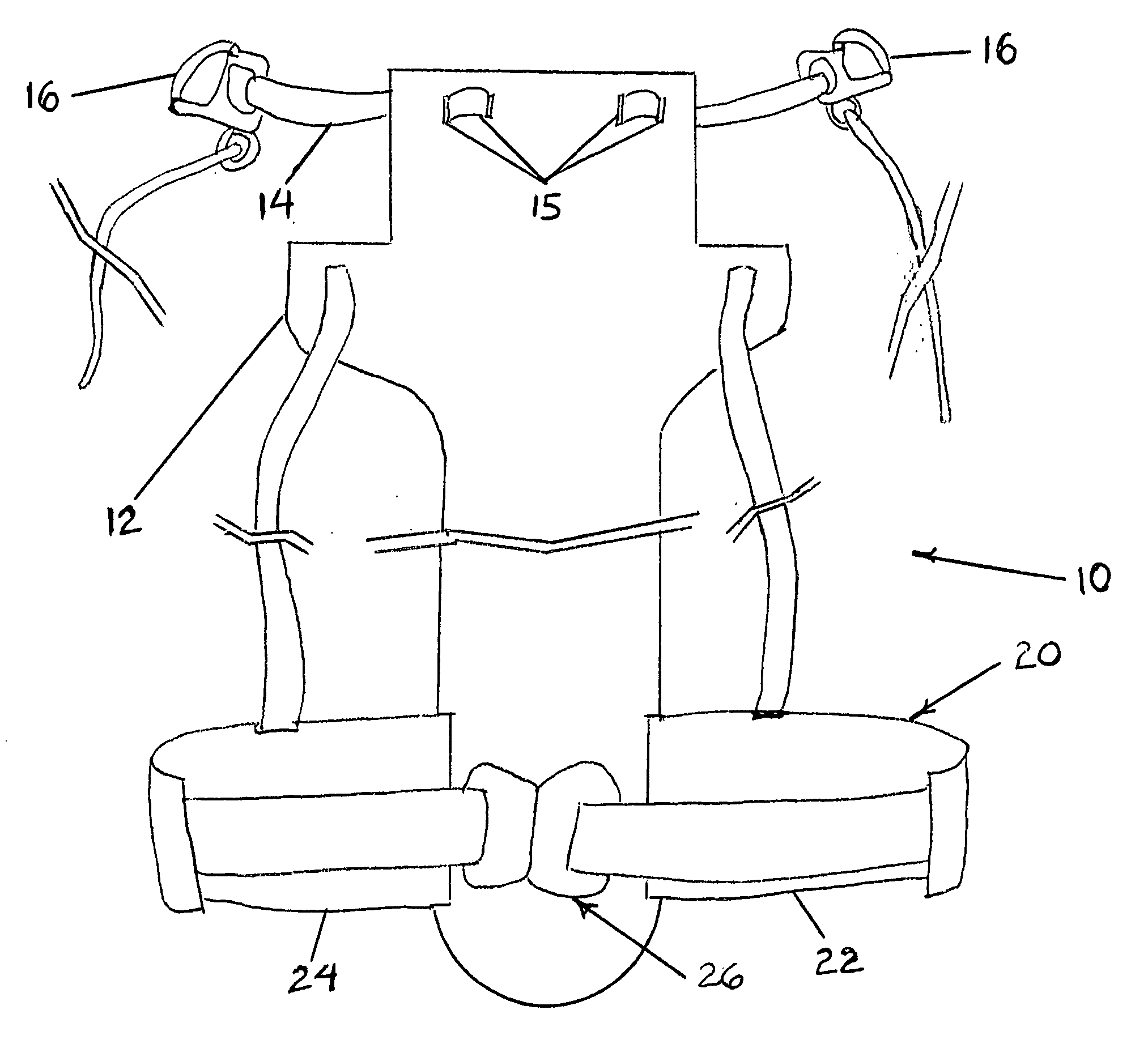
[0036] The invented helmet restraint device controls a driver's head and neck during a high-deceleration event, particularly during a frontal collision of a high performance vehicle. The restraint device is self-contained, not requiring attachment to the vehicle's seat belt assembly or any other portion of the vehicle in order to be fully operable. Instead, the restraint device is anchored to the driver's upper torso to restraint the driver's head from uncontrollably snapping forward and downward during a high-deceleration event.

[0037] During normal operation, the device does not impede the driver's mobility while operating the vehicle, or while entering or exiting the vehicle. During an impact, the device transfers forces from the helmet, through the device, to the driver's upper torso to keep the head and neck in general alignment with the spine, thus obviating possible injury otherwise caused by the driver's head snapping forward and downward.

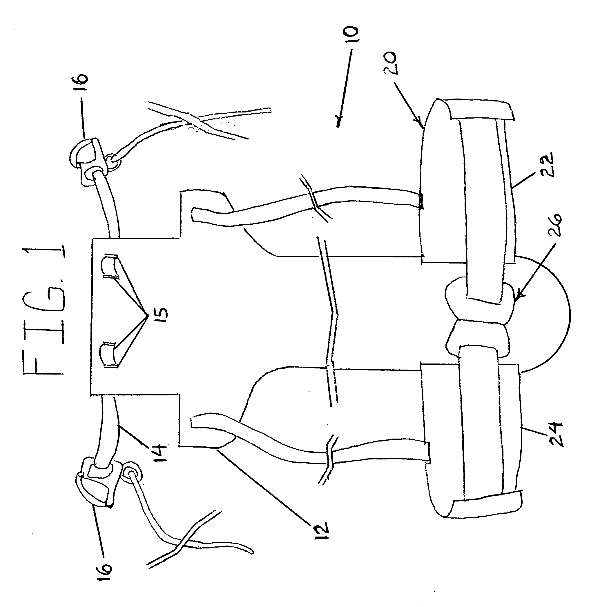
[0038] Referring now to FIG. 1 of t...


PUM


Abstract

A head restraint device worn by a driver while operating a high performance vehicle. The device controls the driver's head from snapping forward and downward during a collision event. The device includes a back member positioned along the back of the driver. The back member is attached to the driver's helmet or skull cap by a first strap. A second strap is configured to encircle the driver's torso in order to releaseably secure the device to the driver. Third straps define openings through which the driver's shoulders are received to assists in holding the device on the driver. During a collision event, forces from the head and helmet are transferred through the first strap and the back member, causing the third strap to react against the mass of the driver's body. These reactive forces control the driver's head and neck from violently moving forward and downward.

Description

CROSS REFERENCE TO RELATED APPLICATIONS [0001] This application claims the benefit of U.S. Provisional Application No. 60 / 409,085, filed Sep. 9, 2002, and which is hereby incorporated by reference.FIELD OF THE INVENTION [0002] The present invention relates to a method and apparatus for controlling a driver's head and neck when subjected to deceleration forces, and more particularly to a device for controlling forward and downward movement of the head and neck of a driver during a frontal crash of a high performance vehicle. BACKGROUND OF THE INVENTION [0003] Currently, drivers of high performance vehicles use a standard five or six point seat belt assembly, in which all the belts tie into a common buckle, to restrain the driver during a crash. The seat belt assembly constrains the torso of the driver from moving substantially away from the seat during a collision. However, the seat belt assembly does not restrain the driver's head or neck, allowing the head to uncontrollably move fo...

Claims


Application Information

Patent Timeline
Patent Type & Authority Applications(United States)
IPC IPC(8): A42B3/04A62B9/04A62B25/00B60N2/48B60R22/00
CPCA42B3/0473A62B9/04B60R22/001B60N2/4802A62B25/00B60N2/803
Inventor ASHLINE, TREVOR P.
Owner SAFETY DYNAMICS
Why Eureka
Try Eureka