Method and apparatus to adaptively cool a welding-type system

a welding type and adaptive cooling technology, applied in the field of welding type systems, can solve the problems of certain welding processes, increasing the heat of the welding torch, and generating a considerable amount of heat during the welding process

Active Publication Date: 2005-01-27
ILLINOIS TOOL WORKS INC
View PDF14 Cites 74 Cited by
  • Summary
  • Abstract
  • Description
  • Claims
  • Application Information

AI Technical Summary

Benefits of technology

[0011] In accordance with yet another aspect of the invention, a method for cooling a welding-type component includes the step of detecting activation of a welding-type component. The method further includes that the steps automatically circulating coolant through the welding-type component upon activation of the welding-type component and maintaining coolant circulation through the welding-type component for a limited period after the welding-type component is deactivated.

Problems solved by technology

It is well known that certain welding processes such as heavy-duty TIG (tungsten inert gas) welding generate a considerable amount of heat during the welding process.
The heat generated, however, can cause the welding torch to become increasingly heated.
One of the drawbacks with these standard cooling systems is that the cooling system is manually operable.
It can therefore be problematic if the operator forgets to turn the cooling system on before commencing welding.
As a result, the temperature of the torch quickly rises to maximum acceptable limits and if not immediately cooled, can cause the torch to break down and malfunction.
It is also costly to interrupt the welding process and allow the torch to cool.
Moreover, the operator may forget to turn off the cooling system during extended periods of downtime.
As such, the cooling system continues to circulate coolant to the welding torch even when cooling is not needed which increases energy consumption and causes premature wear out of components.
Another disadvantage of manually actuated cooling system rests in that the operator may turn off the cooling system prematurely following completion of a welding session.
However, if the operator prematurely shuts down the cooling system, the temperature of the torch may actually increase for a short and potentially damaging period.
These drawbacks can significantly reduce the life expectancy of the cooling system and / or torch and increase the overall energy consumption of the system.
All of which increases the costs of the welding system.

Method used


Image

  • Method and apparatus to adaptively cool a welding-type system
  • Method and apparatus to adaptively cool a welding-type system
  • Method and apparatus to adaptively cool a welding-type system

Examples


Embodiment Construction

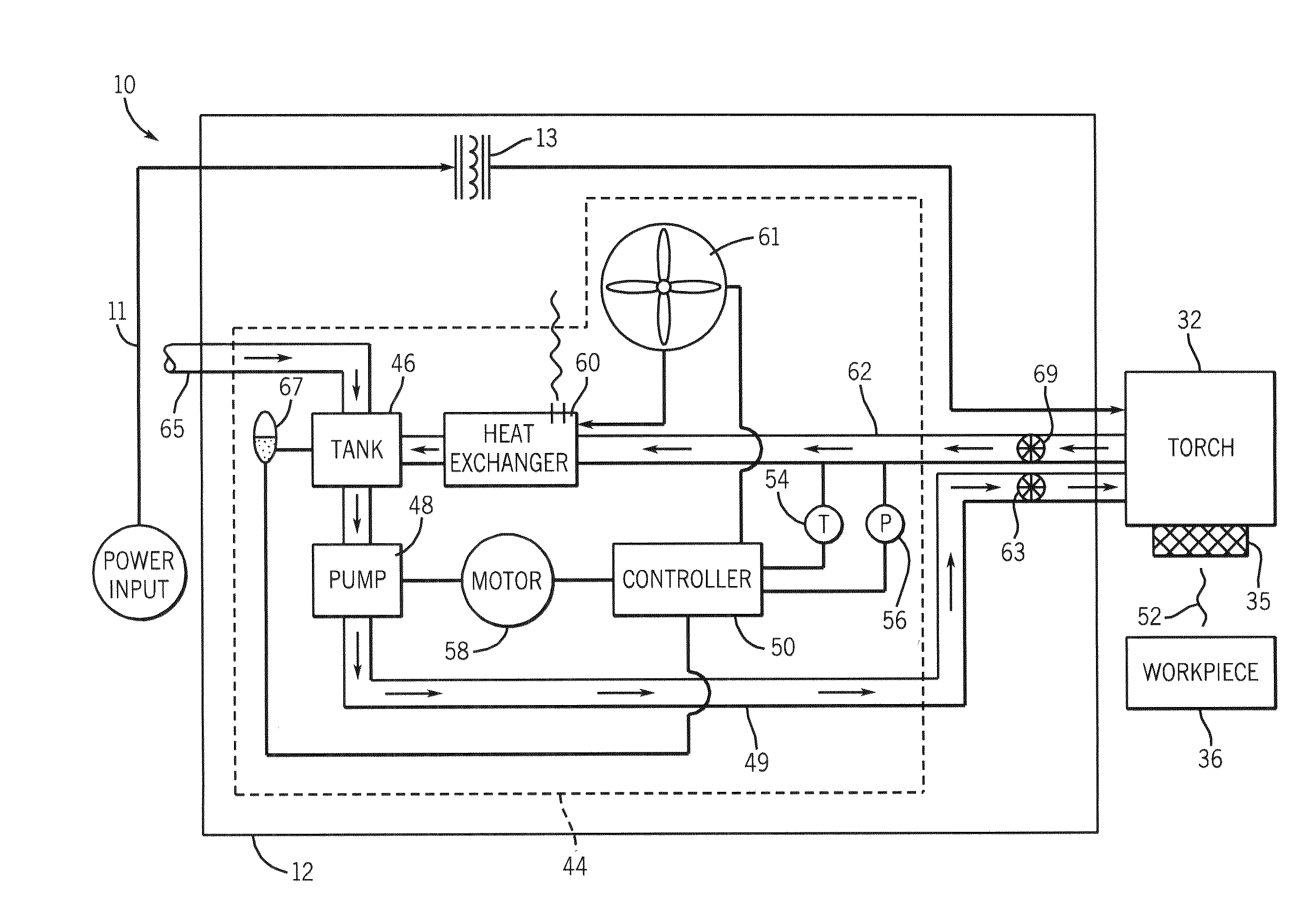
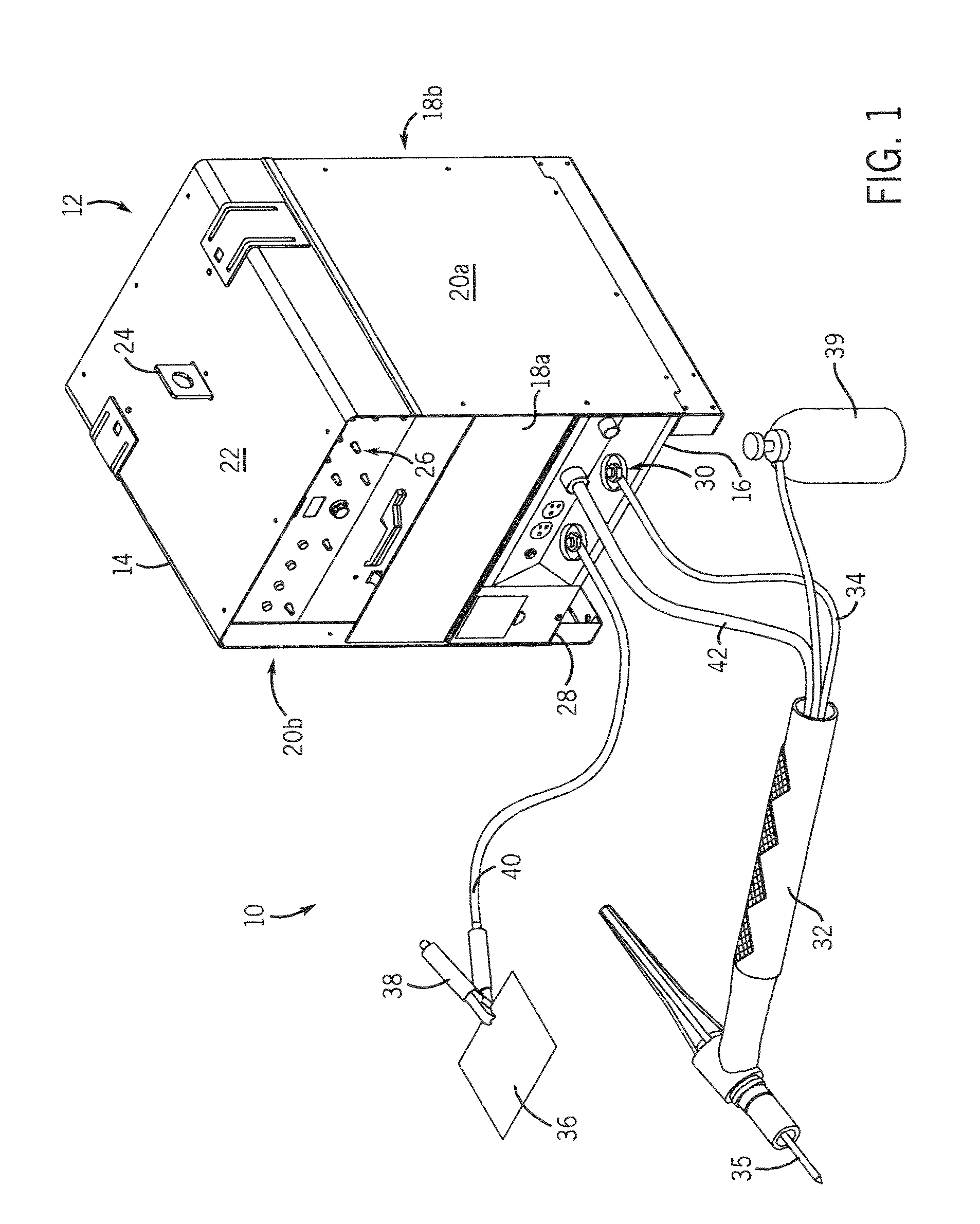
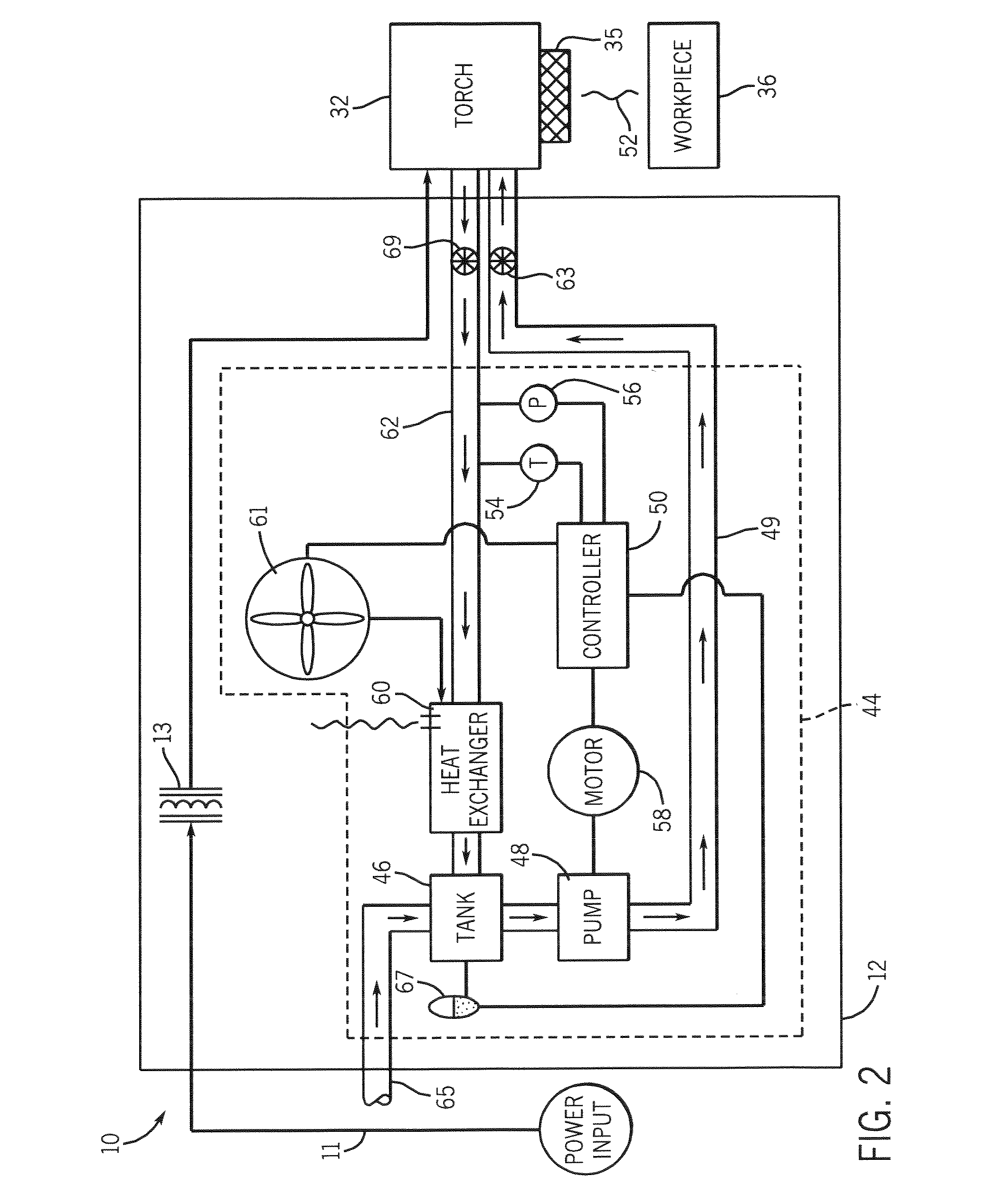
[0021]FIG. 1 is a perspective view of a welding-type system 10 suitable for a number of welding processes including tungsten inert gas (TIG) welding and stick welding. The welding-type system 10 includes a power source 12 disposed within an enclosure 14. Enclosure 14 is defined by a base 16, front and back panels 18a, 18b, and a pair of side panels 20a, 20b attached to the base 16. A top cover 22 having a lifting means 24 is secured to the pair of side panels 20a, 20b to form enclosure 14. The front panel includes control knobs 26 and outlets and receptacles 28 to facilitate connection of welding accessories to the enclosure. For example, an electrode weld output terminal 30 is used to connect a torch or other welding-type component 32 to the power source via cable 34. The torch is designed to hold a tungsten electrode 35. To complete a welding circuit, a workpiece 36 is introduced to a weld by a clamp 38 that is also connected to the power source by cable 40. A gas cylinder 39 is u...


PUM

PropertyMeasurementUnit
melting pointaaaaaaaaaa
timeaaaaaaaaaa
temperatureaaaaaaaaaa

Abstract

A cooling system connected to provide coolant to a welding-type component automatically circulates coolant through the welding component upon activation of the welding component. A controller is configured to regulate the cooling system such that upon activation of the welding-type component coolant is caused to at least flow through the welding-type component and circulate after deactivation of the welding torch until a temperature of the coolant falls below a certain value or a specified time period has expired.

Description

CROSS REFERENCE TO RELATED APPLICATIONS [0001] The present invention is a continuation-in-part and claims priority of U.S. Ser. No. 10 / 604,459 filed Jul. 23, 2003, which is incorporated herein by reference.BACKGROUND OF INVENTION [0002] The present invention relates generally to welding-type systems and, more particularly, to a method and apparatus of an automatically and conditionally cooling a welding-type system upon activation of the welding-type system. More particularly, the invention relates to circulating coolant automatically through a power source and a welding-type torch upon initiation of a welding-type process. [0003] It is well known that certain welding processes such as heavy-duty TIG (tungsten inert gas) welding generate a considerable amount of heat during the welding process. A welding component or welding torch is commonly used to hold a tungsten electrode that is heated to join metals through heat transfer. Because tungsten is a rare metallic element with an ext...

Claims


Application Information

Patent Timeline
Patent Type & Authority Applications(United States)
IPC IPC(8): B23K9/167B23K9/28B23K9/29B23K9/32
CPCB23K9/167B23K9/323B23K9/296B23K9/285
Inventor STEIN, ALAN E.WERBA, DAVID A.GADAMUS, JEFFERY J.LAUER, LEROY H. JR.PAQUETTE, JUSTIN L.SAMMONS, MICHAEL
Owner ILLINOIS TOOL WORKS INC
Why Eureka
Try Eureka