Underrun protection device

a protection device and underrun technology, applied in the direction of bumpers, vehicle components, pedestrian/occupant safety arrangements, etc., can solve the problems of passenger vehicles slipping into the underside of the frame or load carrier of the vehicle, serious road traffic safety risks, and pedestrian injuries to the passengers of the vehicl

Inactive Publication Date: 2005-01-27
VOLVO LASTVAGNAR AB
View PDF6 Cites 19 Cited by
  • Summary
  • Abstract
  • Description
  • Claims
  • Application Information

AI Technical Summary

Benefits of technology

[0015] A purpose of the current invention is to provide an improved underrun protection device for trucks that gives a secure function, that fulfils set requirements for energy absorption, and that may be completely or at least almost completely folded away.

Problems solved by technology

The fact that a truck normally has a relatively large road clearance constitutes a serious risk with respect to road traffic safety.
The reason for this is that during a collision between such a truck and a passenger vehicle there is a risk that the passenger vehicle will penetrate in under (run under) the front or rear part of the truck and thus be jammed between the road surface and the underside of the frame or load carrier of the vehicle.
The result may be that the rear part of the truck will enter the passenger compartment of the vehicle with great force, which in turn may cause serious injuries to the passengers of the vehicle.
Such a solution is, however, contrary to the above-mentioned desire for a large road clearance to facilitate driving over rough terrain.
Although this known design in principle gives a good protection against underrun for the passenger vehicle, it does have a disadvantage in that it requires a large number of moving parts, making it unnecessarily complicated and creating a risk of loss of function.
Also, this solution gives little possibility for controlling the energy absorption in a controlled manner during a collision.
The problem with these types of underrun protection devices, however, is that they may obstruct a hook when connecting a trailer, or they may catch during a reversing operation towards an edge or a loading bay.

Method used


Image

  • Underrun protection device
  • Underrun protection device
  • Underrun protection device

Examples


first embodiment

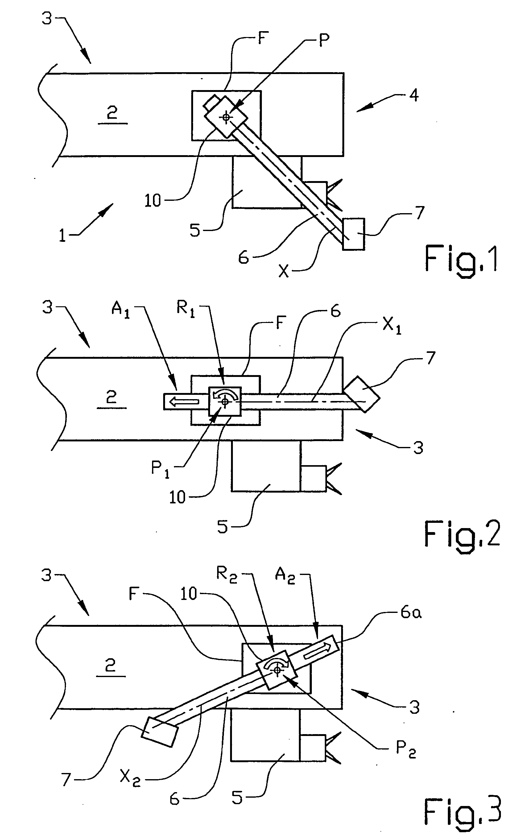
[0062]FIG. 1 shows a side view of a first embodiment according to the invention where a frame for a vehicle, which frame 1 has at least one longitudinal section 2, 3 (only one is shown) and a rear transverse section 4, has been provided with an underrun protection device. In the figure, the underrun protection device is shown in a folded down, active position where it may prevent access to a coupling for a trailer, which coupling is mounted under the frame, as well as reduce the road clearance of the vehicle. In the text below the design of the underrun protection device will be described for one side of the frame 2, unless stated otherwise. All directional references are given in the main direction of movement of the vehicle. The underrun protection device comprises a carrier 6 provided with a transverse impact element 7. The impact element 7 is mounted on at least two carriers 6, placed on either side of the frame, and is positioned slightly behind and below the frame 1.

second embodiment

[0063]FIG. 2 shows a side view of the invention.

[0064] According to this embodiment, the attachment device, F, is provided with a holder 10 that is pivotable relative to the attachment device around a pivoting axis, P. The carrier 6 is displaceable relative to the holder 10, which comprises guiding surfaces enclosing the carrier 6 and co-operates with corresponding guiding surfaces on the carrier. The figure shows the impact element in its active position.

[0065] The guiding surfaces will not be described in detail in this application. These surfaces may preferably have co-operating flat or profiled surfaces or guides, or alternatively a number of cylindrical or profiled rollers running along co-operating guides. The guiding surfaces on a guiding or a guided part respectively, may be placed facing each other or facing away from each other respectively, or vice versa.

[0066]FIG. 2 shows a first method of folding away the underrun protection device according to the first embodiment. A...

third embodiment

[0075] In addition, the invention can be illustrated by FIG. 2.

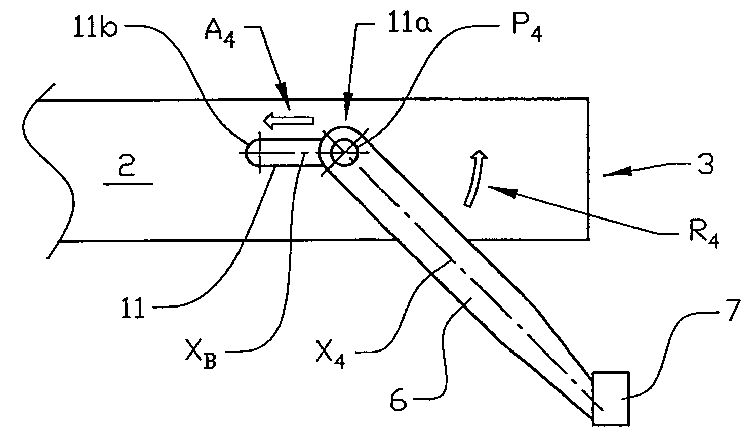
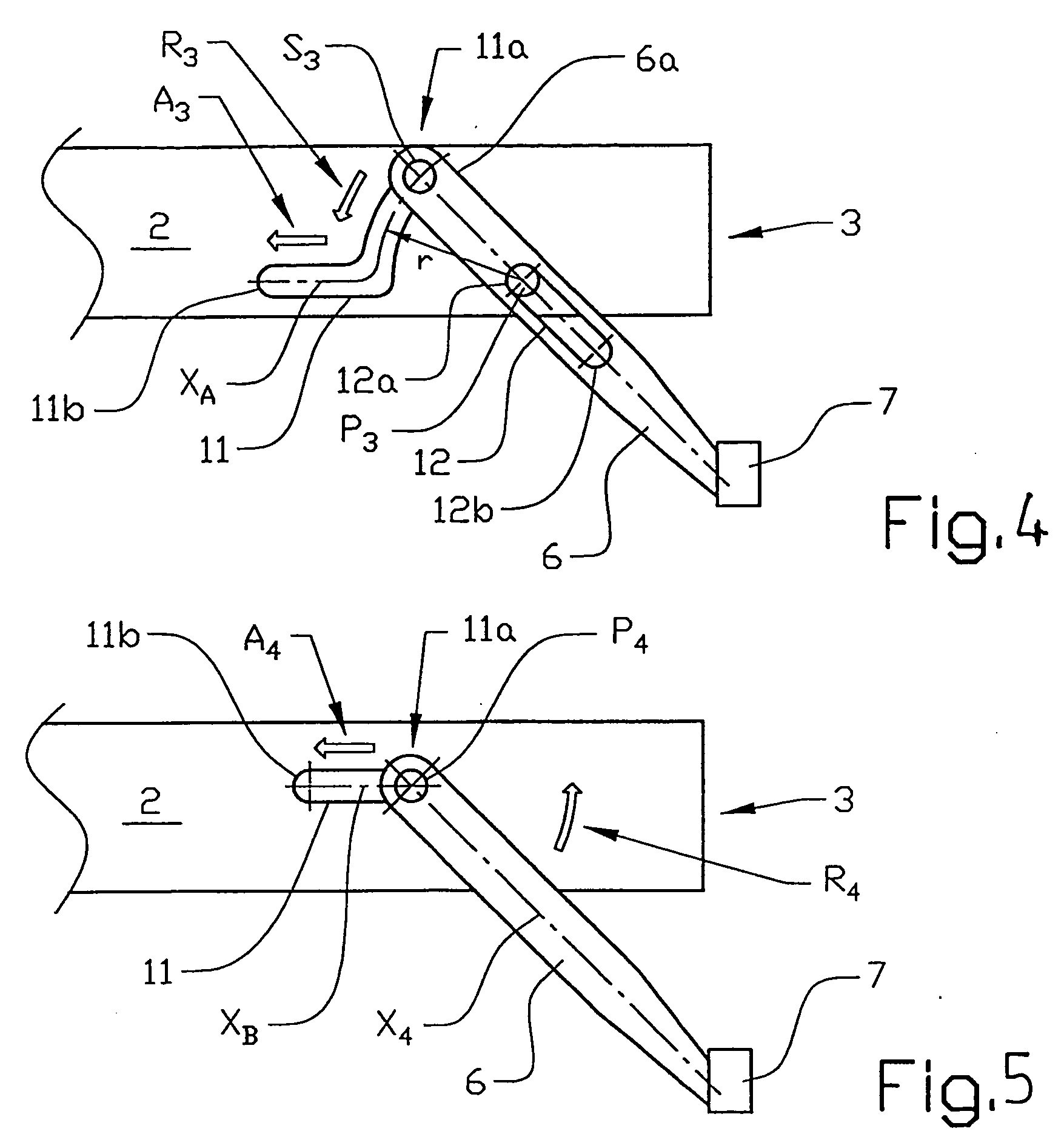
[0076] According to this method the carrier 6 is first displaced from its active position, as shown in FIG. 1, obliquely forwards and upwards relative to the frame 1, as indicated by the arrow A1, to an intermediate position. From this intermediate position the carrier is pivoted backwards and upwards, as indicated by the arrow R1, until the impact element reaches a substantially horizontal position relative to the rear section 4 of the frame 1. The underrun protection device is then in its inactive position.

[0077] This third embodiment can also be achieved by means of guides and guiding slots. One such solution (not shown) comprises a carrier with a guiding slot, as described in connection with FIG. 4; which guiding slot is placed near the first end of the carrier and co-operates with a pivoting axis attached to the frame. The outer part of the first end of the carrier is also provided with a guide, which co-operates w...


PUM


Abstract

Method and arrangement for moving an underrun protection device for vehicles having a frame (3), an impact element (7) arranged on the vehicle at a location corresponding to an expected loading from a force during a possible collision, and at least one displaceable carrier element (6) connecting the frame (3) and the impact element (7). During displacement of the impact element (7) between at least one first, active position and at least one second, inactive position, at least a part of the displacement occurs in a direction that substantially coincides with a longitudinal axis of the carrier (6).

Description

CROSS-REFERENCE TO RELATED APPLICATIONS [0001] The present application is a continuation patent application of International Application No. PCT / SE02 / 01976 filed 30 Oct. 2002 which was published in English pursuant to Article 21(2) of the Patent Cooperation Treaty, and which claims priority to both Swedish Application No. 0104419-7 filed Dec. 21, 2001. Said applications are expressly incorporated herein by reference in their entireties.TECHNICAL FIELD [0002] The current invention relates to a method for maneuvering an underrun protection device and an arrangement for an underrun protection (also known as run-under protection) device for a vehicle. The main area of application for the invention is heavy trucks, especially for the purpose of preventing passenger vehicles from penetrating under a truck during a collision. BACKGROUND ART [0003] Large vehicles, such as trucks, are currently designed with a relatively large road clearance. One major reason for this is the need for using t...

Claims


Application Information

Patent Timeline
Patent Type & Authority Applications(United States)
IPC IPC(8): B60R19/04B60R19/14B60R19/38B60R19/56B60R21/00
CPCB60R19/04B60R19/14B60R2021/0011B60R19/56B60R19/38
Inventor REGNELL, HANSGUSTAFSSON, JENS
Owner VOLVO LASTVAGNAR AB
Why Eureka
Try Eureka