Rotary injection molding apparatus and method for use

Inactive Publication Date: 2005-01-27
VMI HOLLAND BV
View PDF31 Cites 13 Cited by
  • Summary
  • Abstract
  • Description
  • Claims
  • Application Information

AI Technical Summary

Benefits of technology

[0010] The present invention provides a safe, simple and more efficient injection molding apparatus and method for injection molding elastomeric products by using multiple single cavit

Problems solved by technology

Also, changes to the single cavity molds can be impleme

Method used


Image

  • Rotary injection molding apparatus and method for use
  • Rotary injection molding apparatus and method for use
  • Rotary injection molding apparatus and method for use

Examples


Example

DETAILED DESCRIPTION OF THE DRAWINGS

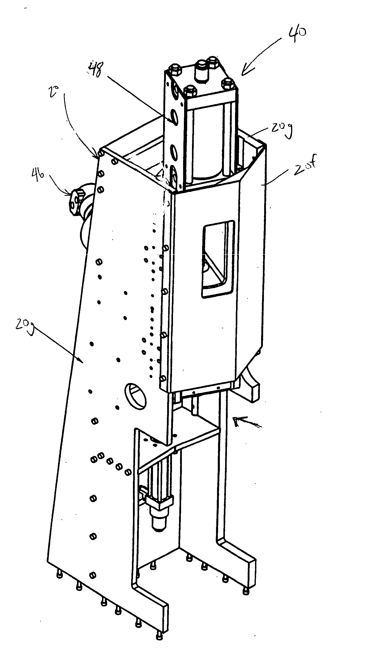
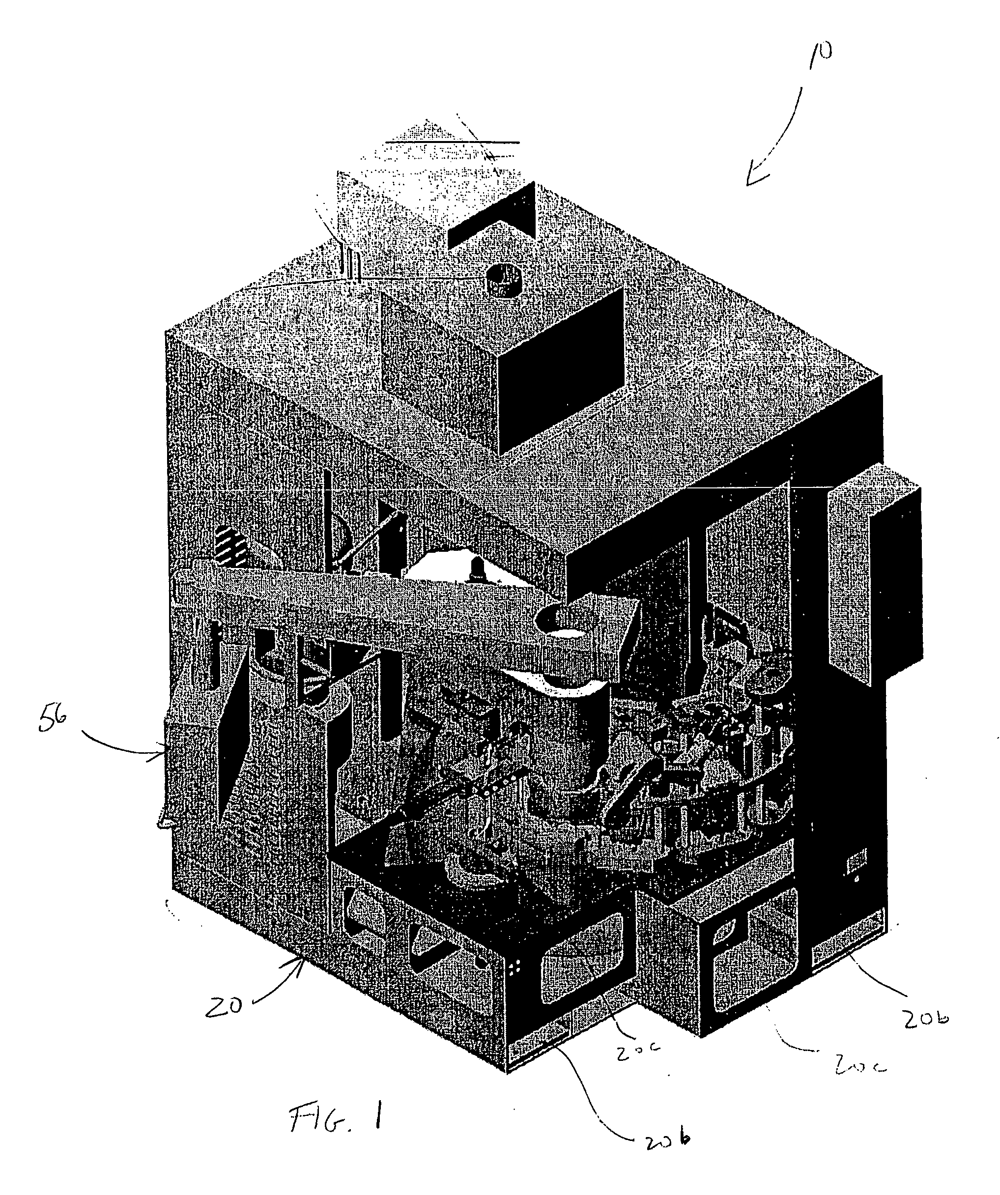
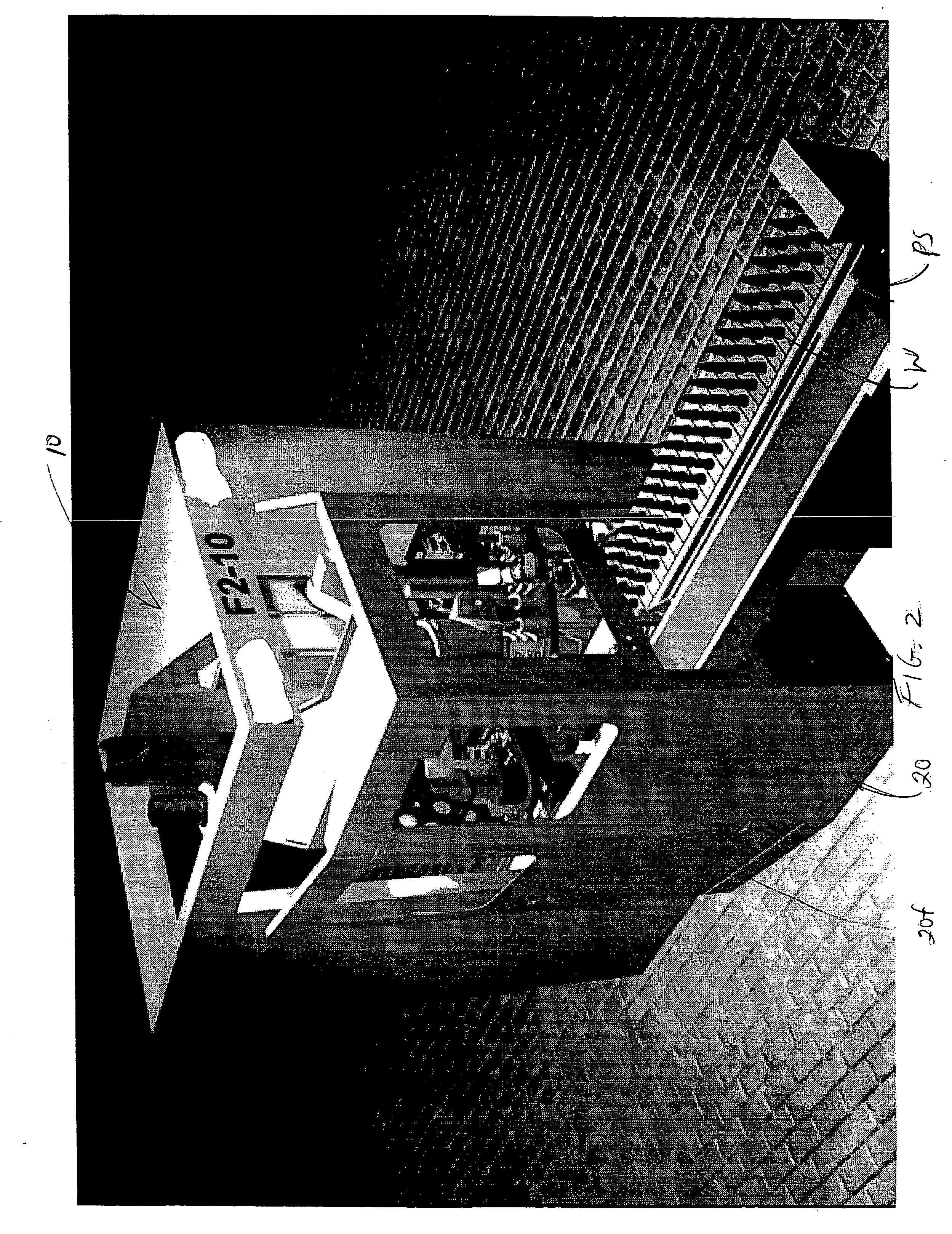
[0056] Turning now to the illustrations of the present embodiment, a multi station rotary injection molding apparatus 10 provides high production injection molding of manufactured products M. In the illustrated embodiment, the rotary injection molding apparatus 10 is supported on a modular frame 20 and includes a rotating table 22 having 10 work stations 24 positioned along the periphery of the rotating table 22. Independent clamp assemblies 28 are supported on the rotating table for engagement with a single extruder and injector assembly, also supported on the modular frame 20. In the preferred embodiment of the apparatus, cure times for manufactured products M are between approximately 75 to 160 seconds per product, and preferably approximately 80 seconds per product. With small multi-section single cavity molds 30, cycle times for movement between positions or stations may be 20 to 30 seconds.

[0057] All press operations are automatic and cont...


PUM

PropertyMeasurementUnit
Timeaaaaaaaaaa
Angleaaaaaaaaaa
Angleaaaaaaaaaa

Abstract

A rotary injection molding apparatus and method for manufacturing products containing elastomeric material within multi-section single cavity molds. The apparatus includes a modular frame supporting an injection molding operation station having an injector assembly with a pressure sensitive nozzle assembly. The injector assembly is engaged with an extruder assembly at a check valve assembly. A mold servicer assembly is provided for assembly and disassembly of multi-section single cavity molds. A robotic arm assembly is supported on the modular frame and positioned for inserting and removing products or product components from disassembled molds. Finally; a rotating table is provided on the frame which has a plurality of work station positions supporting clamping assemblies for clamping single cavity molds around the periphery of the rotating table.

Description

CROSS-REFERENCE TO RELATED APPLICATIONS [0001] The present application claims priority from U.S. patent application Ser. No. 60 / 455,275 filed Mar. 17, 2003, the entire subject matter of which is incorporated herein by reference.BACKGROUND OF THE INVENTION [0002] 1. Field of Invention [0003] The present invention relates to invention molding machines and more specifically to a rotary injection molding apparatus and method for its use. [0004] 2. Background of the Related Art [0005] Injection molding machines are commonly used in the manufacturing industry for molding elastomeric materials such as rubber, plastic or combinations of these materials. For example, current vibration control components for the automotive industry are produced using large injection press machinery with multi-cavity molds. Multi-cavity molds produce large amounts of natural rubber waste from the large runner-system, cavity flash, and damaged cavities. The time and cost to engineer and manufacture these intric...

Claims


Application Information

Patent Timeline
IPC IPC(8): B29C45/06B29C45/14B29C45/42B29C45/54
CPCB29C45/06B29C45/14008B29K2021/00B29C45/54B29C2045/425B29C45/42
Inventor BOYD, KATHLEEN C.BOYD, THOMAS J.
Owner VMI HOLLAND BV
Why Eureka
Try Eureka