Electrical connector

a technology of electrical connectors and connectors, applied in the direction of printed circuit aspects, sustainable manufacturing/processing, final product manufacturing, etc., can solve the problems of short circuits degrade electrical performance, etc., and achieve the effect of preventing short circuits

Inactive Publication Date: 2005-01-27
JU TED
View PDF1 Cites 11 Cited by
  • Summary
  • Abstract
  • Description
  • Claims
  • Application Information

AI Technical Summary

Benefits of technology

[0005] It is therefore an object of the invention to provide an electrical connector that prevents solde...

Problems solved by technology

However, this causes another problem: the solder material 4 is squeezed by a circuit board 6 to flow upward if the circuit board 6 is not perfectly flat.
In this manner, the solder material in adjacent sockets 1 may come into contact with one another to cause a short circuit and degrade electrical ...

Method used


Image

  • Electrical connector
  • Electrical connector
  • Electrical connector

Examples


Embodiment Construction

[0021] Wherever possible in the following description, like reference numerals will refer to like elements and parts unless otherwise illustrated.

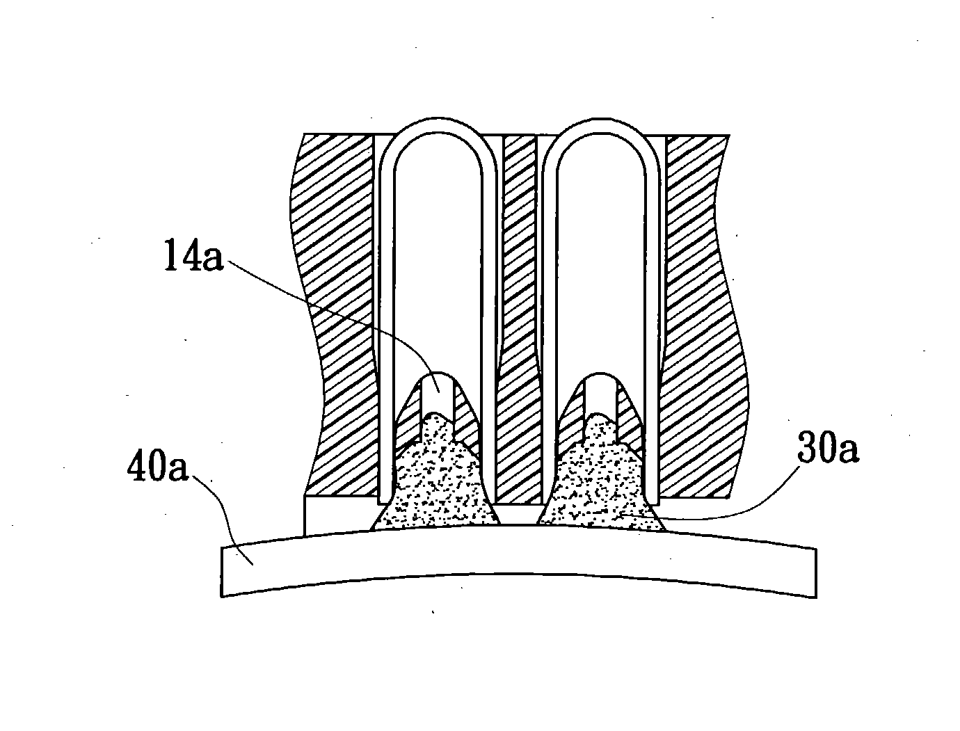
[0022] Referring to FIG. 5 and FIG. 6, an electrical connector of the invention includes an insulator 10a having a plurality of terminal slots 11a. A plurality of reversed U-shaped terminals 20a and solder materials 30 are respectively mounted inside the terminal slots 11a. A standoff 13a is formed inside each terminal slot 11a to contact with a tip of each terminal 20a. An accommodating space 12a is defined above the standoff 13a for receiving solder materials 30a. An overflow hole 14a is formed approximately at a center of standoff 13a. When the circuit board 40a is to be assembled, the solder material 30a is melted. If the circuit board 40a is not perfectly flat, then the solder material 30a is squeezed and consequently spreads out. With the overflow holes 14a, the solder materials 30a flow along the overflow holes 14a, preventing the ...


PUM


Abstract

An electrical connector is bonded to a circuit board by solder materials. The solder materials are well arranged so that no short circuits occur. The electrical connector can be applied in a wide range of uses with high yield and reduced cost. The electrical connector has an insulator having a plurality of terminals and a solder material therein. The electrical connector is characterized by the insulator being provided with a plurality of overflow holes in a direction along which the insulator and terminals apply pressure to the solder material.

Description

BACKGROUND OF THE INVENTION [0001] 1. Field of the Invention [0002] The invention relates to an electrical connector, and more particularly, to an electrical connector having an insulator with an overflow hole. [0003] 2. Description of the Related Art [0004] Referring to FIG. 1 and FIG. 2, a conventional electrical connector includes an insulator 2 with a plurality of sockets 1, a terminal 3 and a plurality of solder materials 4 located inside the sockets 1. In order to prevent the solder material 4 from climbing up along the terminals 3 after being melted, which may result in soldering failure, a standoff 5 is formed in each socket 1. However, this causes another problem: the solder material 4 is squeezed by a circuit board 6 to flow upward if the circuit board 6 is not perfectly flat. There is no space to accommodate the solder material or to ventilate the air 7, so that the solder material 4 is forced to flow out through sides of the corresponding socket 1. In this manner, the so...

Claims


Application Information

Patent Timeline
IPC IPC(8): H01R4/02H01R12/00H05K3/34
CPCH01R4/028H05K3/3426H05K2203/046H05K2201/1084H05K2201/10189Y02P70/50
Inventor JU, TED
Owner JU TED
Why Eureka
Try Eureka