Thermal micro-valves for micro-integrated devices

a technology of micro-integrated devices and thermal micro-valves, which is applied in the direction of valve operating devices/release devices, transportation and packaging, laboratory glassware, etc., can solve the problems of complex integrated systems that can be easily assembled into multi-component devices, and achieve the effect of preventing short circuits and/or damage to electronic elements, and enhancing the degree of mixing in a merged microdropl

Active Publication Date: 2007-03-27
RGT UNIV OF MICHIGAN
View PDF4 Cites 106 Cited by
  • Summary
  • Abstract
  • Description
  • Claims
  • Application Information

AI Technical Summary

Benefits of technology

[0042]“Liquid barrier” or “moisture barrier” is any structure or treatment process on existing structures that prevents short circuits and / or damage to electronic elements (e.g., prevents the destruction of the aluminum heating elements). In one embodiment of the present invention, the liquid barrier comprises a first silicon oxide layer, a silicon nitride layer, and a second silicon oxide layer.
[0043]“Merging” is distinct from “mixing.” When a first and second microdroplet is merged to create a merged microdroplet, the liquid may or may not be mixed. Moreover, the degree of mixing in a merged microdroplet can be enhanced by a variety of techniques contemplated by the present invention, including but not limited to reversing the flow direction of the merged microdroplet.

Problems solved by technology

Since all of the components are made using conventional photolithographic techniques, multi-component devices can be readily assembled into complex, integrated systems.

Method used


Image

  • Thermal micro-valves for micro-integrated devices
  • Thermal micro-valves for micro-integrated devices
  • Thermal micro-valves for micro-integrated devices

Examples


example 1

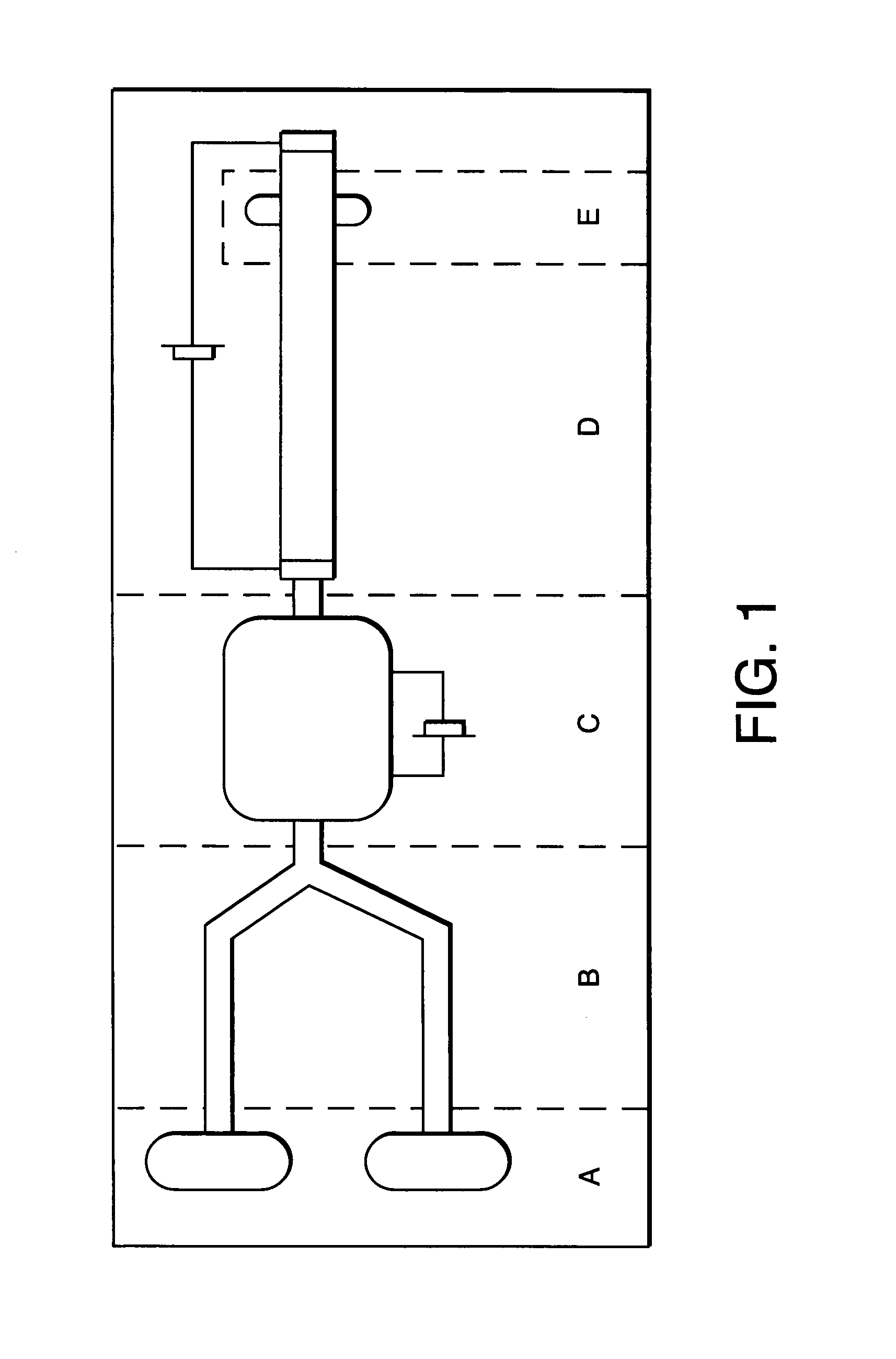
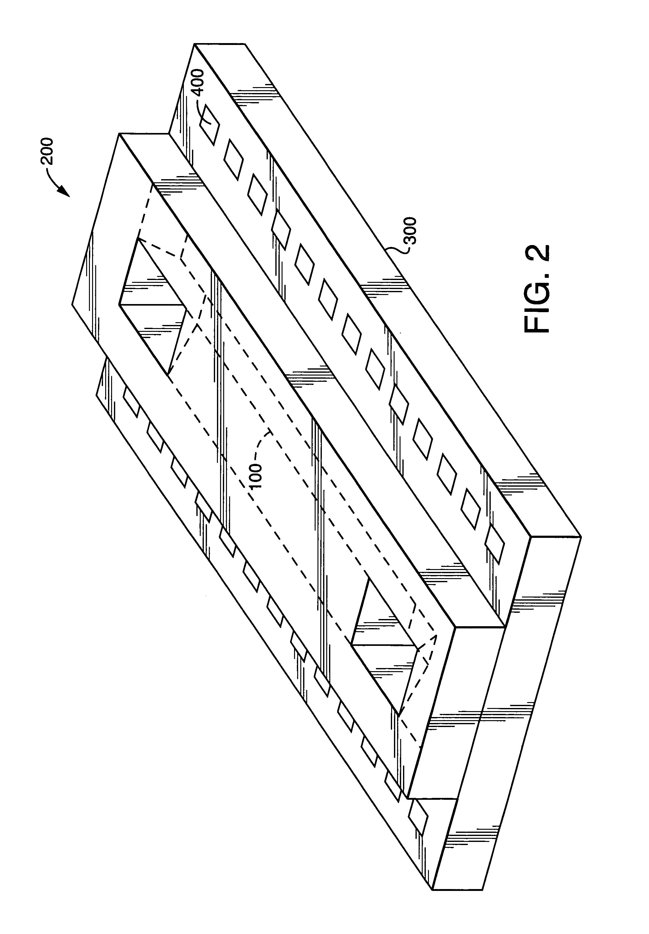
[0219]In this example, a microdevice is fabricated as per U.S. Pat. No. 7,048,734 to Burns et al. and which is herein incorporated by reference. The test structure is very simple. The main part is constructed from a two mask process with five layers of materials on top of the Si substrate. Proceeding from the lowest to the uppermost layer, the SiO2 serves as an insulator between the Si substrate and the other metal layers, which function as solder pads and heating elements. The Ti layer (250 Å) is for adhesion of Ni. The layers of Ni (1000 Å) and Au (1000 Å) act as a diffusion barrier for the solder. The Au layer also serves as a wettable pad. Finally, the layer of solder is for bonding two substrates together. The solder will melt by heating the metal layers. Another substrate that will be bonded has the same construction except for the solder.

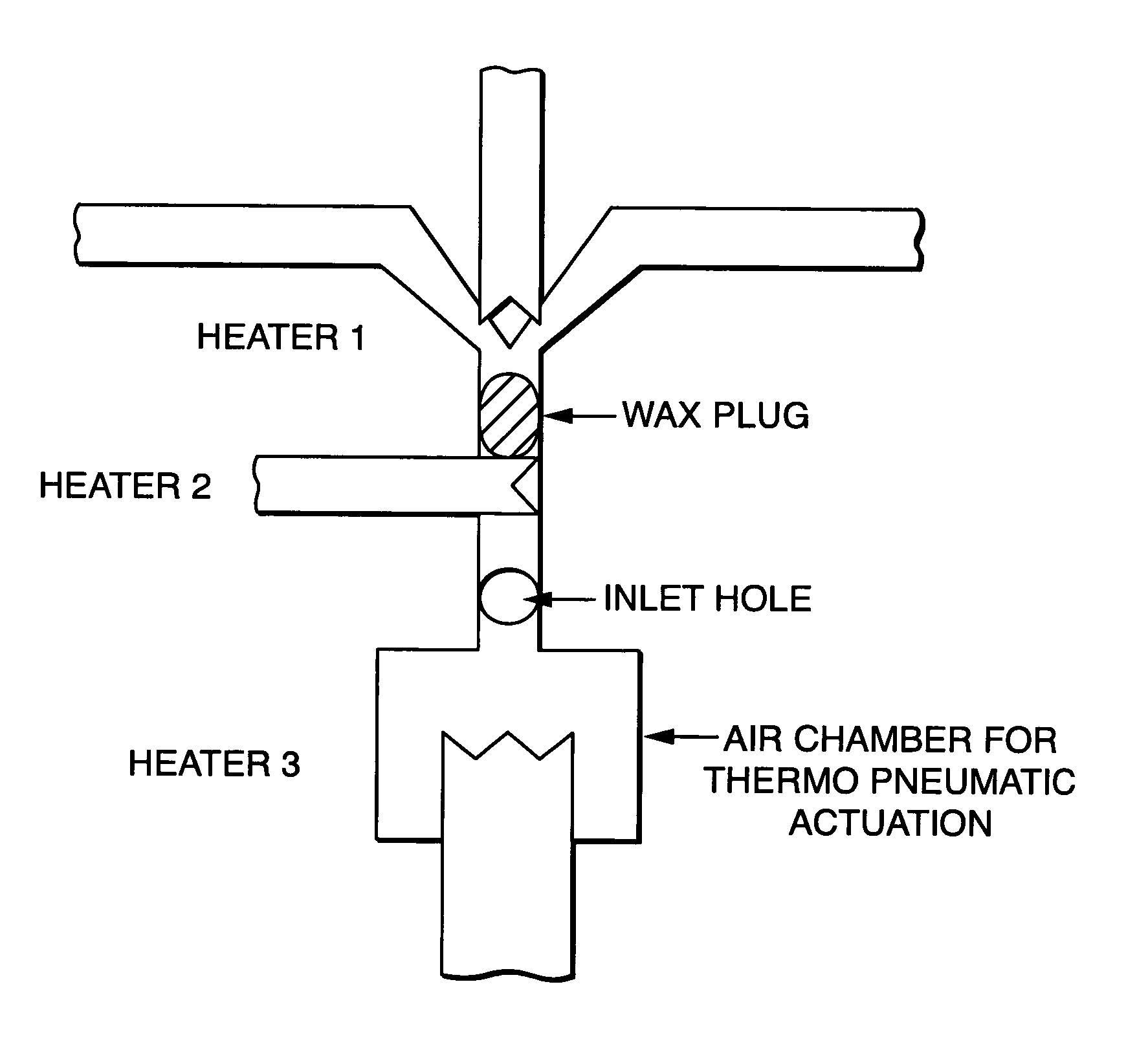
[0220]A thermo-pneumatic microvalve is utilized in the test structure. A corrugated diaphragm is chosen for its larger deflection and higher...

example 2

[0227]Design of the Microfluidic Phase Transition Latch Valve. The Primary objective of this work was to construct a microvalve network that would replace external valving for fluidic manipulation on the integrated device. Central for realizing complex fluid motion is an easy-to-fabricate microvalve. For discrete drop systems flow regulation is generally not a concern. An on-off valve to selectively open or close lines would suffice for most of the fluidic manipulation on an integrated system. It is very important that the valve be designed for efficient functioning of the integrated device. The success of the valve was measured against the efficient performance of the integrated device. The single unit valve is compatible with the biochemistry. The valve should introduce few (preferably zero) additional steps to the photolithographic fabrication strategy for integrated devices. Additionally, the valve is electronically addressable. Finally, in order to have a complex network the in...

example 3

[0231]This example examined the properties of several different waxes for use in the valves of the present invention.

[0232]The viscosity of wax was measured as a function of temperature on a constant stress rheometer. The oscillation mode on a cone and plate rheometer was used. The oscillation frequency was set to 6.283 rad / s while the geometry gap was set to 44 microns. All pure waxes showed a sharp transition from liquid to solid at the melting point. Wax mixtures were used to tailor melting points. Wax mixture 2 was a blend of 50% paraffin wax (melting point=49° C.) and 50% M1595 synthetic wax (melting point=85° C.). Upon cooling, this mixture showed a sharp transition around 79–81° C. and then the viscosity gradually increased to the solid phase value till 49° C. which is the melting point of the paraffin wax. Wax mixture 1 which has 25% paraffin and 75% M1595 had a transition around 72–75° C.

[0233]The biocompatibility of the waxes for use in lab-on-a-chip application was tested...


PUM


Abstract

The movement and mixing of microdroplets through microchannels is described employing silicon-based microscale devices, comprising microdroplet transport channels, reaction regions, electrophoresis modules, and radiation detectors. The discrete droplets are differentially heated and propelled through etched channels. Electronic components are fabricated on the same substrate material, allowing sensors and controlling circuitry to be incorporated in the same device.

Description

[0001]This is a conversion of the Provisional Application No. 60 / 423,594 filed on Nov. 4, 2002.[0002]This work was funded in part by NIH grant number R01-HG01406. The government may have certain rights in the invention.FIELD OF THE INVENTION[0003]The present invention relates to microfabrication of microscale devices and reactions in microscale devices, and in particular, movement of biological samples in microdroplets through microchannels to initiate biological reactions. More particularly, the present invention relates to phase change latched valves for micro-integrated devices.BACKGROUND[0004]Current bioassay technologies are adequate for the detailed analysis of samples that range in number from hundreds to thousands per year. Projects requiring on the order of millions of assays, however, are beyond the capabilities of today's laboratories because of the current inefficiencies in (i) liquid handling of reagent and DNA template solutions, (ii) measurement of solution volumes, (...

Claims


Application Information

Patent Timeline
Patent Type & Authority Patents(United States)
IPC IPC(8): F15C1/04F16K13/10B01F13/00B01J19/00B01L3/00F15C5/00F16K99/00
CPCF16K99/0015F16K99/0001F16K99/0019F16K99/0036F16K99/0044B01F13/0059B01J19/0093B01L3/502738F16K99/0017F16K2099/0074F16K2099/0076F16K2099/0084B01J2219/00783B01J2219/00788B01J2219/00828B01J2219/00873B01J2219/00889B01J2219/00891B01L3/502707B01L3/502784B01L2200/12B01L2400/0487B01L2400/0677Y10T137/2196Y10T137/4643B01F33/30
Inventor BURNS, MARK A.PAL, ROHIT
Owner RGT UNIV OF MICHIGAN
Why Eureka
Try Eureka