Ambulatory robot and method for controlling the same

a technology of ambulatory robots and robots, which is applied in the field of ambulatory robots, can solve the problems of inability to be widely used in practical applications, increased weight and volume of driving motors, and inferiority of bipedal ambulatory robots according to the prior art in terms of maximum advance speed

Inactive Publication Date: 2005-01-27
SAMSUNG ELECTRONICS CO LTD
View PDF25 Cites 15 Cited by
  • Summary
  • Abstract
  • Description
  • Claims
  • Application Information

AI Technical Summary

Benefits of technology

The present invention has been made in an effort to solve at least some of the above-mentioned problems occurring in the prior art. A feature of an embodiment of the present invention is to provide an ambulatory robot that performs walking and running motions depending on the surrounding circumstances without requiring larger actuators, and a method for controlling the robot.
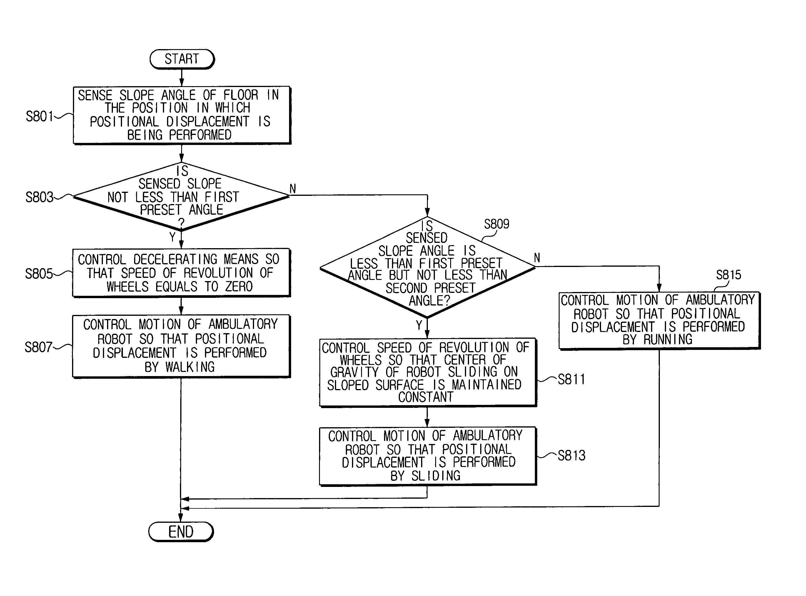
According to another feature of an embodiment of the present invention, there is provided a method for controlling an ambulatory robot, the ambulatory robot including a lower body part having two or more legs and an upper body part installed on an upper end of the lower body part and performing positional displacement by moving the lower body part, the method including sensing a slope of a floor, controlling a speed of revolution of a rotating means that is installed on a bottom surface of each of the two or more legs based on the slope of the floor, and controlling a motion of the ambulatory robot using the upper and lower body parts so that the positional displacement of the robot is performed by any of running, walking or sliding, depending on the controlled speed of revolution.

Problems solved by technology

They cannot, however, be widely used in practical applications, because they are only able to move on a flat surface and are not able to traverse a non-flat area, such as a step, a doorsill, or other similar obstacle.
In addition, because four-wheeled movable robots are driven by a motor, they have a problem in that the weight and volume of the driving motor is necessarily increased in order to exert torque sufficient for enduring the loads of the four-wheeled robots.
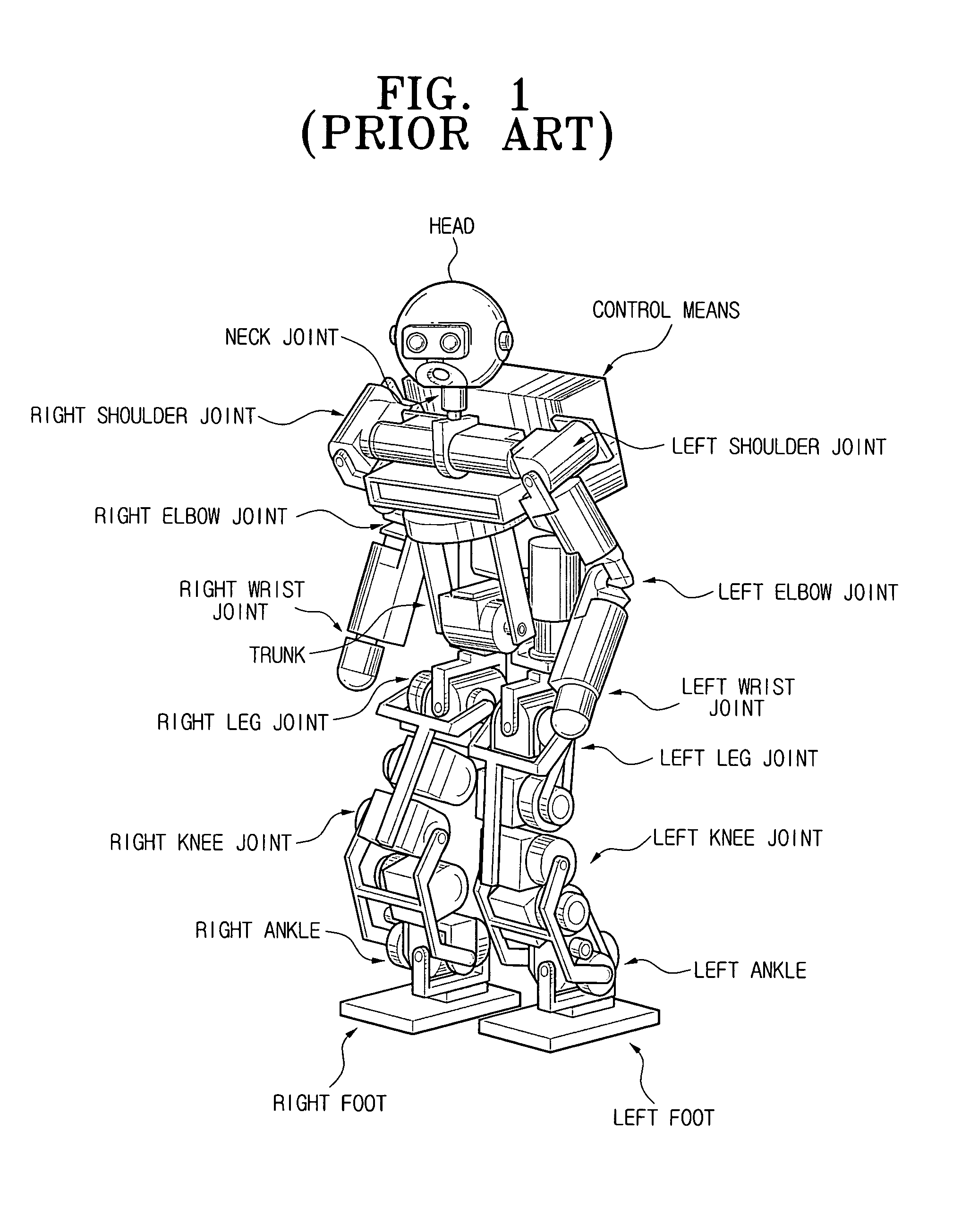
However, bipedal ambulatory robots according to the prior art are inferior to general wheel-type robots in terms of maximum advance speed.
It is difficult, however, to produce an amount of torque needed for a robot to run with existing actuators.

Method used


Image

  • Ambulatory robot and method for controlling the same
  • Ambulatory robot and method for controlling the same
  • Ambulatory robot and method for controlling the same

Examples


Embodiment Construction

Korean Application No. 2003-5076, filed Jan. 25, 2003, and entitled: “Ambulatory Robot and Method for Controlling the Same,” is incorporated by reference herein in its entirety.

The present invention will now be described more fully hereinafter with reference to the accompanying drawings, in which preferred embodiments of the invention are shown. The invention may, however, be embodied in different forms and should not be construed as limited to the embodiments set forth herein. Rather, these embodiments are provided so that this disclosure will be thorough and complete, and will fully convey the scope of the invention to those skilled in the art. Like reference numerals refer to like elements throughout.

FIG. 4 illustrates an example of an ambulatory robot according to an embodiment of the present invention. Herein, the ambulatory robot will be described with reference to a bipedal ambulatory robot with two feet by way of example. Referring to the drawing, the bipedal ambulatory ...


PUM


Abstract

An ambulatory robot including a lower body part having two or more legs and an upper body part installed on an upper end of the lower body part and capable of performing positional displacement by moving the lower body part, includes slope-detection means for sensing a slope of a floor, rotating means installed on a bottom surface of each of the two or more legs, and control means for controlling a motion of the ambulatory robot using the lower and upper body parts, wherein the control means controls a speed of revolution of the rotating means based on the slope of the floor, and controls the motion of the ambulatory robot so that the positional displacement of the ambulatory robot is performed by any of running, walking and sliding, depending on the controlled speed of revolution.

Description

BACKGROUND OF THE INVENTION 1. Field of the Invention The present invention relates to an ambulatory robot and a method for controlling the same. More particularly, the present invention relates to an ambulatory robot that performs a combination of wheel type movements and leg type movements and a method for controlling the ambulatory robot. 2. Description of the Related Art The most basic apparatus for driving a movable robot is a four-wheeled driving apparatus. Four-wheeled movable robots have been widely used in industrial fields since the 1970's. Recently, movable robots have been used as cleaning robots, monitoring robots, serving robots, and the like. Four-wheeled movable robots have an advantage in that they are able to run stably without falling. They cannot, however, be widely used in practical applications, because they are only able to move on a flat surface and are not able to traverse a non-flat area, such as a step, a doorsill, or other similar obstacle. In additio...

Claims


Application Information

Patent Timeline
Patent Type & Authority Applications(United States)
IPC IPC(8): B25J5/00A63H11/00B62D57/032
CPCA63H11/00B62D57/032A63H2200/00E02D3/10E02D2200/1671
Inventor KWON, WOONGLEE, SUK-HAN
Owner SAMSUNG ELECTRONICS CO LTD
Why Eureka
Try Eureka