
Knock-on sweep structure

a technology of retaining structure and screw, which is applied in the field of tillage tools, can solve the problems of affecting the operation the retaining device has suffered from one or more bolts, and the bolts must be removed, etc., and achieves the effect of improving the retaining structure of the retaining device, simple and inexpensive manufacturing and assembly, and reliably holding the retaining devi

Inactive Publication Date: 2005-02-03
DEERE & CO
View PDF26 Cites 3 Cited by
  • Summary
  • Abstract
  • Description
  • Claims
  • Application Information

AI Technical Summary

Benefits of technology

[0005] It is therefore an object of the present invention to provide an improved sweep retaining structure for a knock-on sweep that overcomes one or more of the above-mentioned problems. It is another object to provide such an improved sweep retaining structure which is simple and inexpensive to manufacture and assemble and yet reliably holds the sweep on the shank and facilitates quick and easy attachment and removal of the sweep.
[0006] It is yet another object to provide an improved sweep retaining structure which provides reliable retention independently of manufacturing tolerances. It is a further object to provide such a structure having simplified and more reliable sweep attachment which requires less mounting force when initially attaching a sweep so the sweep can be attached by hand.
[0008] Sweep retaining structure includes a retainer having a contact end biased towards the sweep. The sweep includes two or more spaced retainer-receiving areas to accommodate manufacturing tolerances and facilitate hand mounting. In one embodiment, the retainer is a wire made of spring steel having a contact end biased against the underside of the sweep. The underside of the sweep includes a series of stepped portions or to provide a ratcheting function. As the sweep is slid onto the adapter on the shank, the contact end springs into a first retaining position on the stepped portion that aligns with the spring end. The first position maintains the sweep on the shank without need to forcibly drive the sweep onto the adaptor, and the attachment can be done by hand-without-tools. The force applied to the sweep during initiation of normal operation moves the sweep into a wedge locked position and provides a self-ratcheting effect for the retainer structure. If tolerances are such that the sweep moves upwardly on the shank beyond a central position, a stepped portion closer to the tip end of the sweep is engaged by the end. If tolerances provide a tighter fit so that the sweep does not move as far up the shank, a stepped portion closer to the upper end of the sweep is engaged.
[0009] To remove the sweep, a tool is used to engage and depress the retainer. In one embodiment, the tool fits behind the stem of the sweep so that a slot in the sweep adjacent the retainer is obviated for improved retainer operation and increased retainer life. The parts can be reversed in an alternate embodiment so that the stepped portions are on the shank or wedge adaptor and the retainer is on the sweep.

Problems solved by technology

When the tool in such an assembly has to be replaced because of wear or damage, the bolts must be removed.
Wear and corrosion of the bolts substantially hinders removal and often makes the replacement a difficult and time-consuming task.
Most retaining devices have suffered from one or more problems, including need for additional parts and the loss of sweeps when encountering high removal forces during transport and during rebounding of the shank from a tripped position.
Such detents generally help retain the sweeps on the shanks, but the forces exerted on a sweep, particularly forces exerted on deep tillage tools, can be so great that the sweep fails to stay on the shank.
The geometry of most previously available sweep detent arrangements, including non-symmetrical mating surfaces on some, usually limits penetration of the retaining surface into the hole so that retaining forces are limited.
Some care must be taken to align the protrusion with the hole, and part tolerances, variations in force used to mount the sweep, or lack of indexing of the clip relative to the shank can make such alignment troublesome.
A relatively small, ramped contact area between the clip and the hole also increases the potential for losing a sweep.
Soil moving up and around the stem portion of the sweep can move the clip from the detent position or wear away the clip until it is ineffective for holding the sweep on the shank.
Extreme forces on the detent, such as those which occur during rebound, can also cause deformation of the detent.
If the detent deforms, loosened sweeps can unacceptably dangle from the shank or be lost.
A common problem with sweep detents is most have a fixed detent position, and manufacturing tolerances in the sweep and support can result in an overly loose or tight fit at the detent position.
If there is excess looseness in the fit between the sweep and sweep adapter, the detent structure may have to bear substantially all the retaining load.
If the fit is too tight, the sweep may never reach the detent position and may be lost during transport or at the end of a shank-rebound.
Providing the manufacturing tolerances necessary for proper alignment can make the cost of the device prohibitive.

Method used


Image

  • Knock-on sweep structure
  • Knock-on sweep structure
  • Knock-on sweep structure

Examples


Embodiment Construction

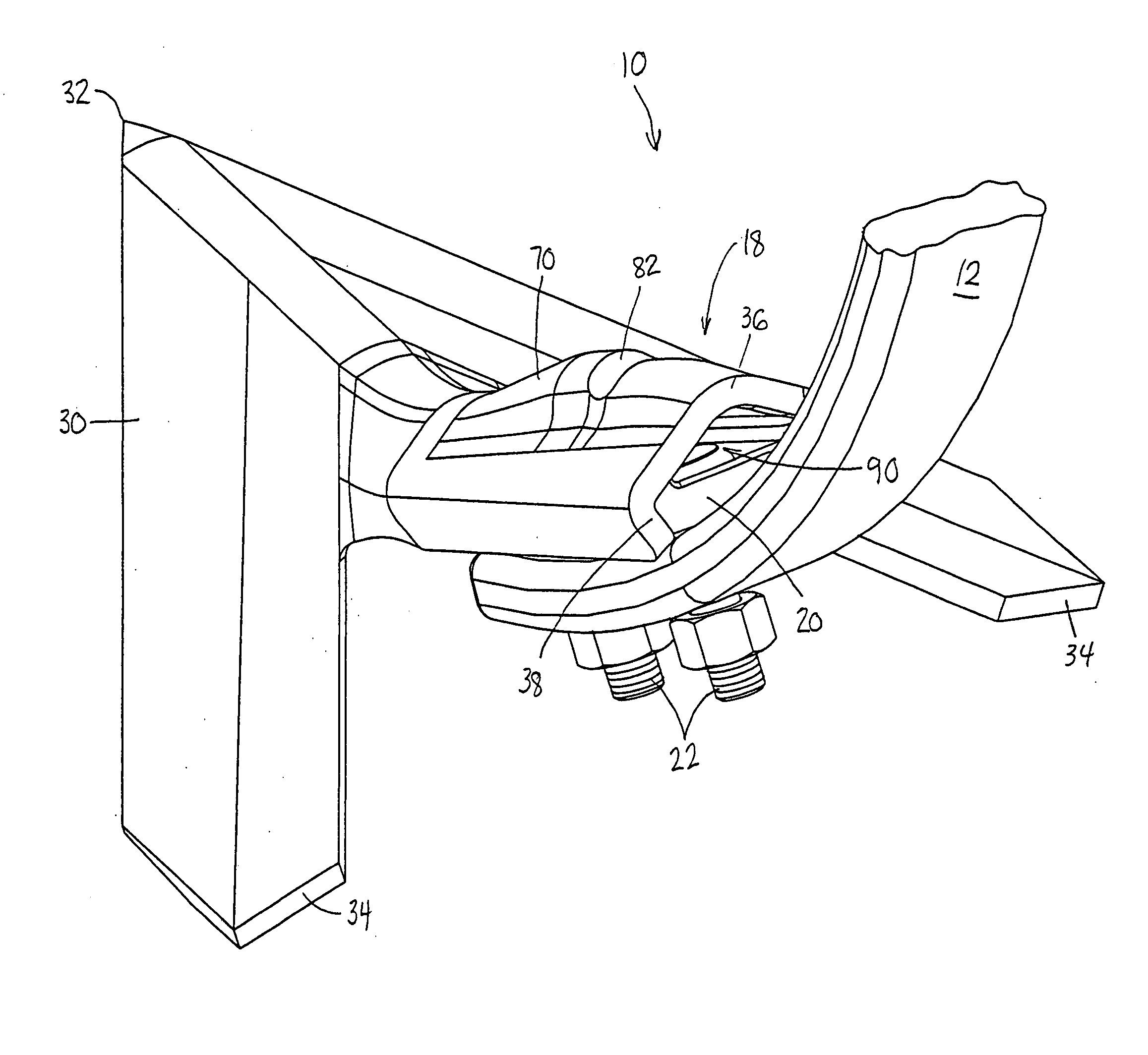
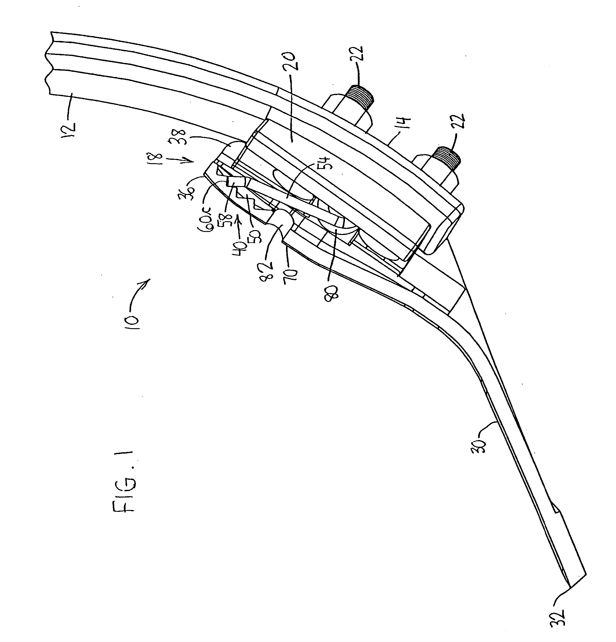
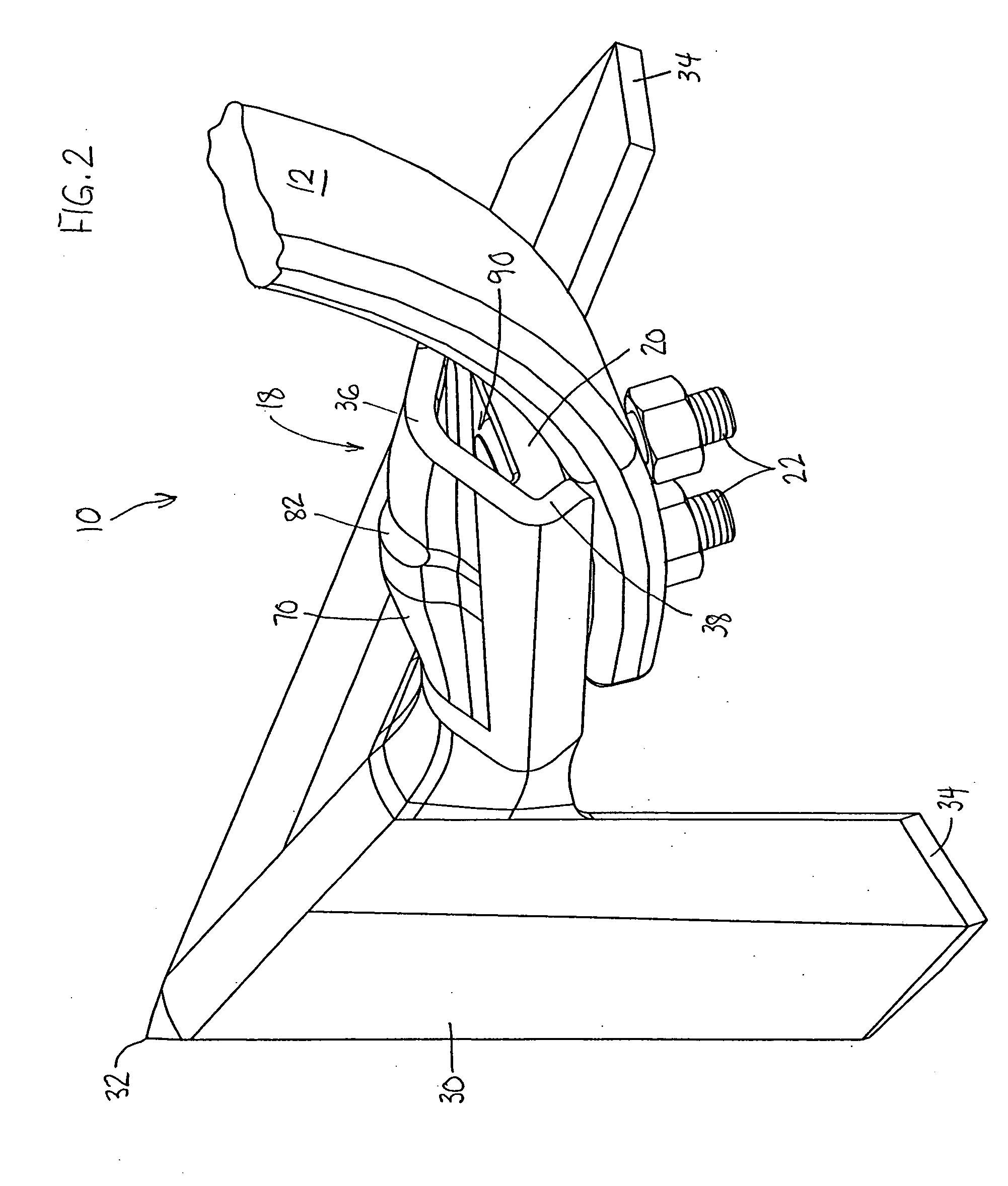
[0018] Referring now to FIG. 1, therein is shown the lower portion of a spring trip shank assembly 10 including a shank 12 having a lower tool-mounting end 14 supporting a knock-on sweep assembly 18. The assembly 18 includes a wedge-shaped adapter bracket or sweep support 20 having an aft face conforming to the forward face of the end 14. The support 20 is secured to the end by two plow bolts 22 extending through apertures in the sweep support 20 and corresponding apertures in the end 14 of the shank 12. An earthworking tool 30, shown as a cultivator sweep in FIGS. 1 and 2, includes a forwardmost tip or point 32 and opposed wing portions 34 diverging outwardly in the rearward direction. An downwardly and rearwardly concave sweep mounting portion or stem 36 includes edges 38 which wrap partially around the sweep support 20. The stem portion 36 provides a wedge fit between the tool 30 and the lower end 14 of the shank 12 when the tool 30 is urged upwardly onto the sweep support 20. Th...


PUM


Abstract

Sweep retaining structure includes a retainer having a contact end biased towards the sweep. The sweep includes two or more spaced end-receiving areas to accommodate changes in the mounted sweep position. In one embodiment, the retainer is a wire made of spring steel having a contact end biased against the underside of the sweep. In one embodiment, the underside of the sweep includes a series of stepped portions. As the sweep is forced on the adapter on the shank, the contact end springs into retaining position on the stepped portion that aligns with the spring end when the sweep is in the mounted position. The sweep can be attached loosely by hand in an initial position with operating forces moving the sweep to a wedge locked position.

Description

FIELD OF THE INVENTION [0001] The present invention relates generally to tillage tools and, more specifically, to a knock-on or fastenerless sweep with structure for preventing a sweep from falling off the end of a shank. BACKGROUND OF THE INVENTION [0002] Standard assemblies for implements such as chisel plows and field cultivators typically include a spring trip shank assembly extending downwardly to a tool-receiving end which mounts a shovel, point or sweep. Previously available mounting structure included bolts extending through holes in the tool and the shank to secure the tool. When the tool in such an assembly has to be replaced because of wear or damage, the bolts must be removed. Wear and corrosion of the bolts substantially hinders removal and often makes the replacement a difficult and time-consuming task. [0003] Several solutions to the problem of easily and quickly replacing worn elements such as sweeps on shanks have been developed over the years, including adapter bra...

Claims


Application Information

Patent Timeline
Patent Type & Authority Applications(United States)
IPC IPC(8): A01B35/22
CPCA01B35/225
Inventor POUTRE, BENOIT JOCELYNHOOK, RICHARD WAYNENOONAN, JAMES THOMASPECK, DONALD RAYEGERT, MICHAEL SIEBEN
Owner DEERE & CO
Learn More