
Electrical connector

a technology of electrical connectors and connectors, applied in the direction of coupling contact members, coupling device connections, coupling devices, etc., can solve the problems of no shielding means and the inability of connectors to provide effective emi shielding, and achieve the effect of reliable signal transmission

Inactive Publication Date: 2005-02-10
HON HAI PRECISION IND CO LTD
View PDF12 Cites 6 Cited by
  • Summary
  • Abstract
  • Description
  • Claims
  • Application Information

AI Technical Summary

Benefits of technology

[0008] Accordingly, one object of the present invention is to provide a new FPC connector, whereby the connector can provide Electro Magnetic Interference (EMI) shielding to ensure reliable signal transmission between the FPC connector and a mated connector.
[0009] Another object of the present invention is to provide a new FPC connector, whereby the connector can reinforce a housing of the connector.
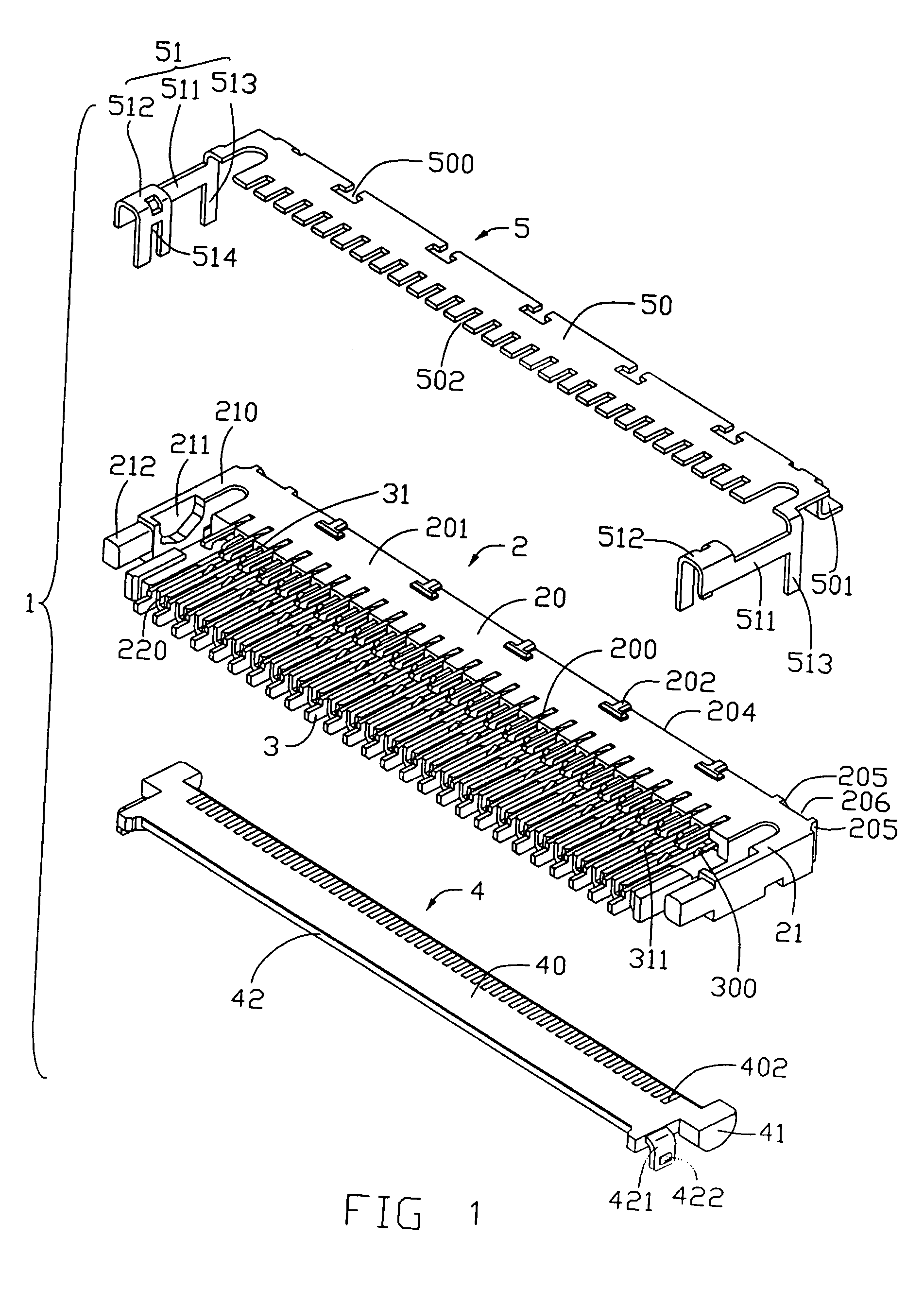
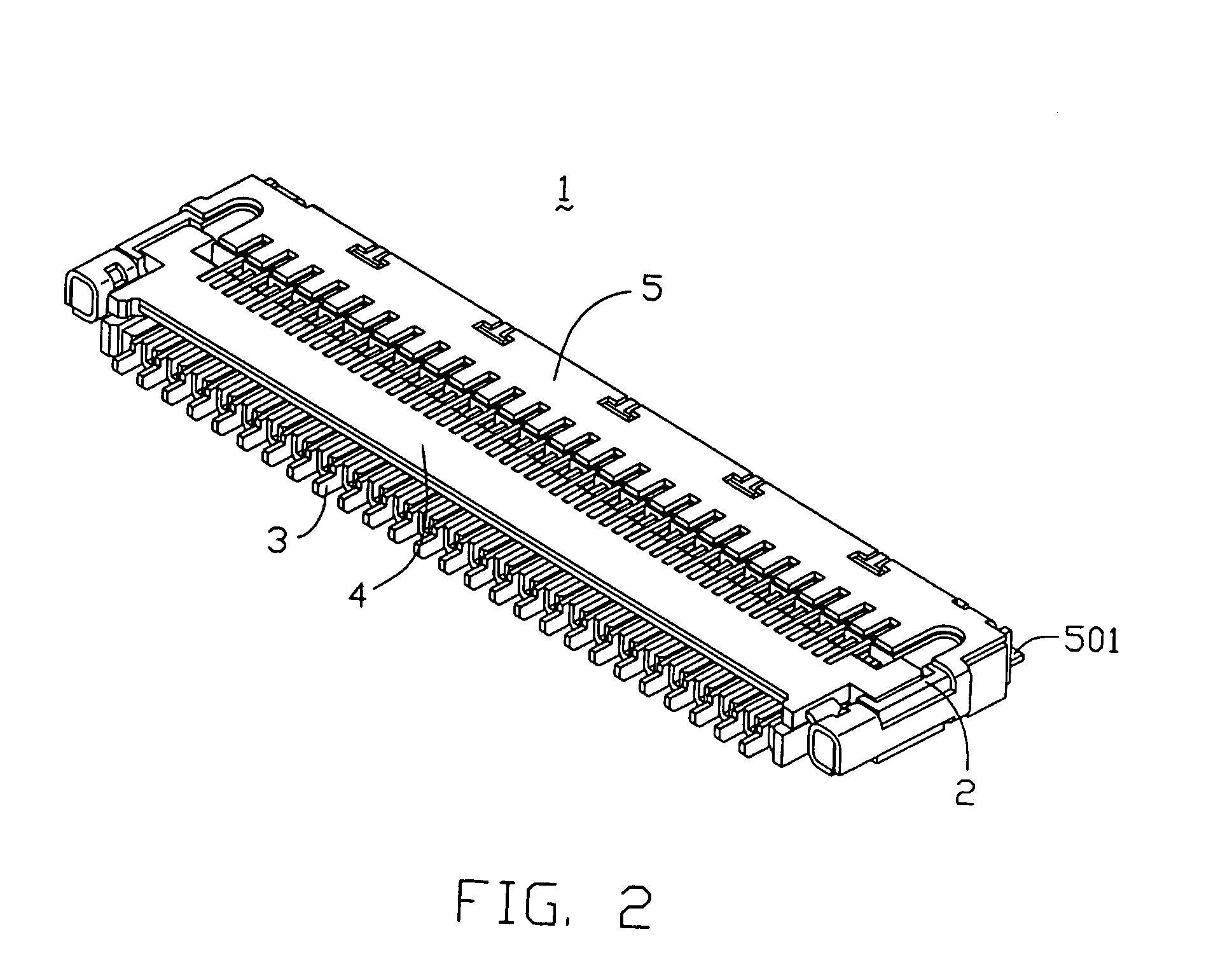
[0010] To achieve the aforementioned objects, an FPC connector in accordance with a preferred embodiment of the present invention is provided. The FPC connector comprises an elongated insulative housing, a plurality of contacts received in the housing and an actuator rotatably mounted to the housing. A shielding is attached to the housing, functioning as an EMI device. The housing has a main body and a pair of side latches extending from two opposite sides of the main body. A plurality of securing protrusions is formed on the main body. A pair of grooves is defined in the main body. The shielding substantially surrounds a top surface of the housing. A plurality of securing slots is defined in the shielding, for engaging with the securing protrusions of the housing. A pair of grounding tabs extends from the shielding, partly retained in the respective grooves of the housing, for mating with corresponding grounding pads of a PCB. A pair of clasping portions is formed on the shielding, surrounding the side latches of the housing. This can also reinforce the strength of the housing.

Problems solved by technology

However, these connectors have a shortcoming that there is no shielding means in these structures.
When transmitting high-frequency signals, these connectors cannot provide effective EMI shielding.

Method used


Image

  • Electrical connector
  • Electrical connector
  • Electrical connector

Examples


Embodiment Construction

[0016] Reference will now be made to the drawings to describe the present invention in detail.

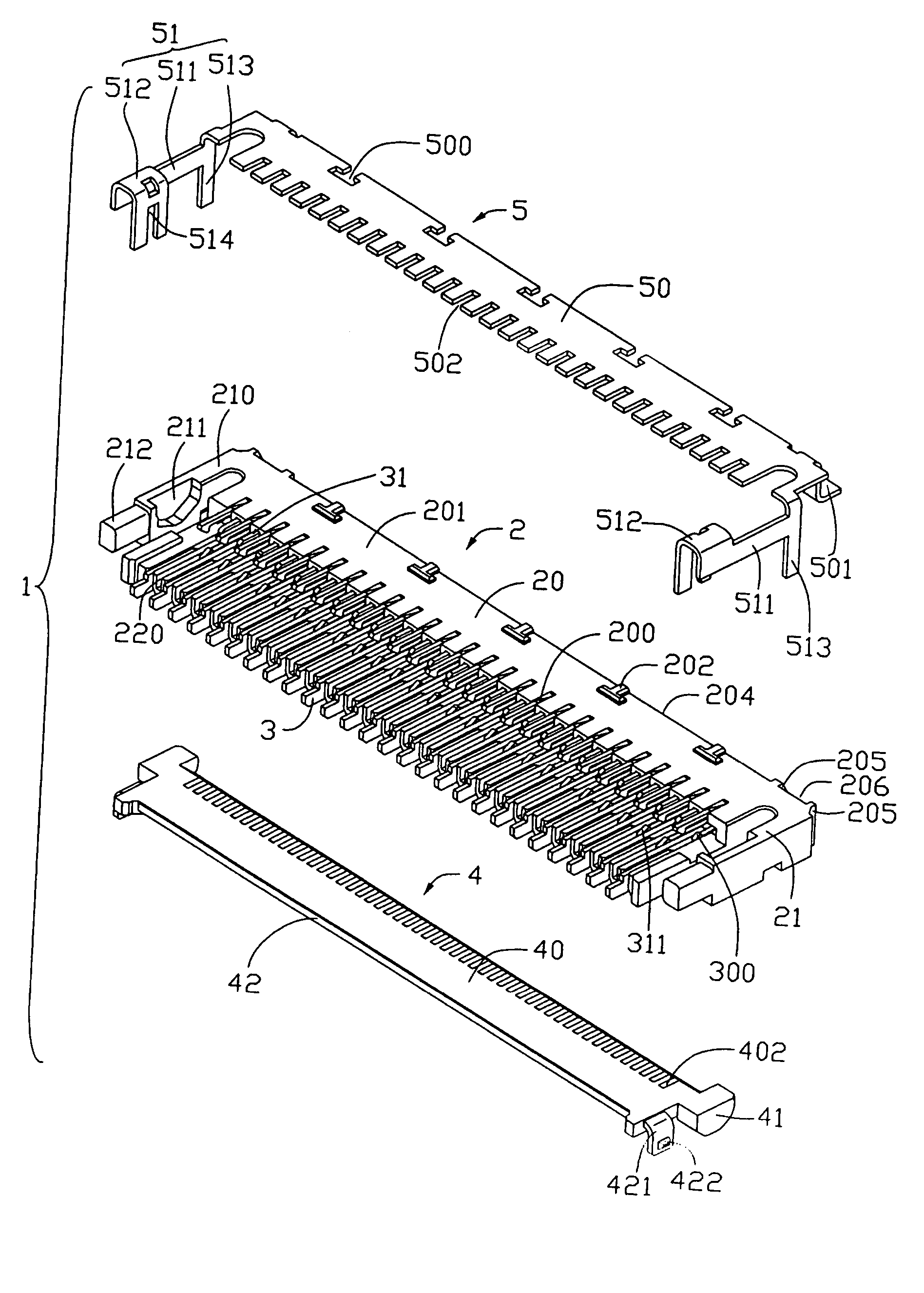
[0017] Referring to FIGS. 1 and 4, an FPC connector 1 in accordance with a preferred embodiment of the present invention is provided for electrically connecting a flexible printed circuit (FPC) (not shown) with a printed circuit board (PCB) (not shown). The FPC connector 1 comprises an insulative housing 2, a plurality of first and second contacts 3,31 received in the housing 2, an actuator 4 rotatably mounted to the housing 2, and a shielding 5 attached to the housing 2.

[0018] The housing 2 is configured with a longitudinal main body 21, and a pair of side latches 21 extends from two opposite sides of the main body 21. A plurality of spaced first and second passageways 200,220 are defined in the main body 20, for receiving the corresponding first and second contacts 3, 31 therein, respectively. The main body 20 has a top surface 201, a bottom surface 203 opposite to the top surface 201, ...


PUM


Abstract

A Flexible Printed Circuit (FPC) connector (1) includes a housing (2), a number of contacts (3,31) received in the housing, an actuator rotatably mounted on the housing, and a shielding (5) attached to the housing. The shielding substantially surrounds a top surface (201) of the housing. A number of securing slots (500) are defined in the shielding and engage with protrusions (202) of the housing for positioning the shielding on the housing. Grounding tabs (501) extend from the shielding for mating with corresponding grounding pads of a PCB. The shielding and the grounding tabs extending therefrom can provide EMI protection to the connector. The shielding can also reinforce the strength of the housing.

Description

BACKGROUND OF THE INVENTION [0001] 1. Field of the Invention [0002] The present invention relates to electrical connectors, and more particularly to a connector for electrically connecting a flexible substrate such as a flexible printed circuit (FPC), to a circuit substrate such as a printed circuit board (PCB). [0003] 2. Description of the Prior Art [0004] Flexible printed circuit (FPC) connectors are widely used for electrically connecting flexible printed circuits to PCBs. A typical FPC connector includes an insulating housing, contact elements received in the housing, an actuator ratatably mounted onto the housing and / or inserted into the housing, for pressing an FPC against the contact elements. [0005] With the miniaturization of electronic system and the development of high-frequency signal transmission technology, A FPC connector used in such system needs to reliably transmit high-frequency signals. A shielding is commonly required to provided for the FPC connector, to preven...

Claims


Application Information

Patent Timeline
Patent Type & Authority Applications(United States)
IPC IPC(8): H01R12/24
CPCH01R23/662H01R12/775H01R12/00
Inventor HUANG, CHIEN HSUN
Owner HON HAI PRECISION IND CO LTD
Learn More