Drive mechanisms suitable for use in drug delivery devices

a technology of driving mechanism and drug delivery device, which is applied in the direction of infusion needles, infusion syringes, other medical devices, etc., can solve the problems of physical infirmity, impaired vision, and the inability to easily correct a set overdose,

Inactive Publication Date: 2005-02-10
SANOFI AVENTIS DEUT GMBH
View PDF9 Cites 120 Cited by
  • Summary
  • Abstract
  • Description
  • Claims
  • Application Information

AI Technical Summary

Problems solved by technology

In the case of those with diabetes, many users will be physically infirm and may also have impaired vision requiring the drive mechanism to have low dispensing force and an easy to read dose setting di...

Method used


Image

  • Drive mechanisms suitable for use in drug delivery devices
  • Drive mechanisms suitable for use in drug delivery devices
  • Drive mechanisms suitable for use in drug delivery devices

Examples


first embodiment

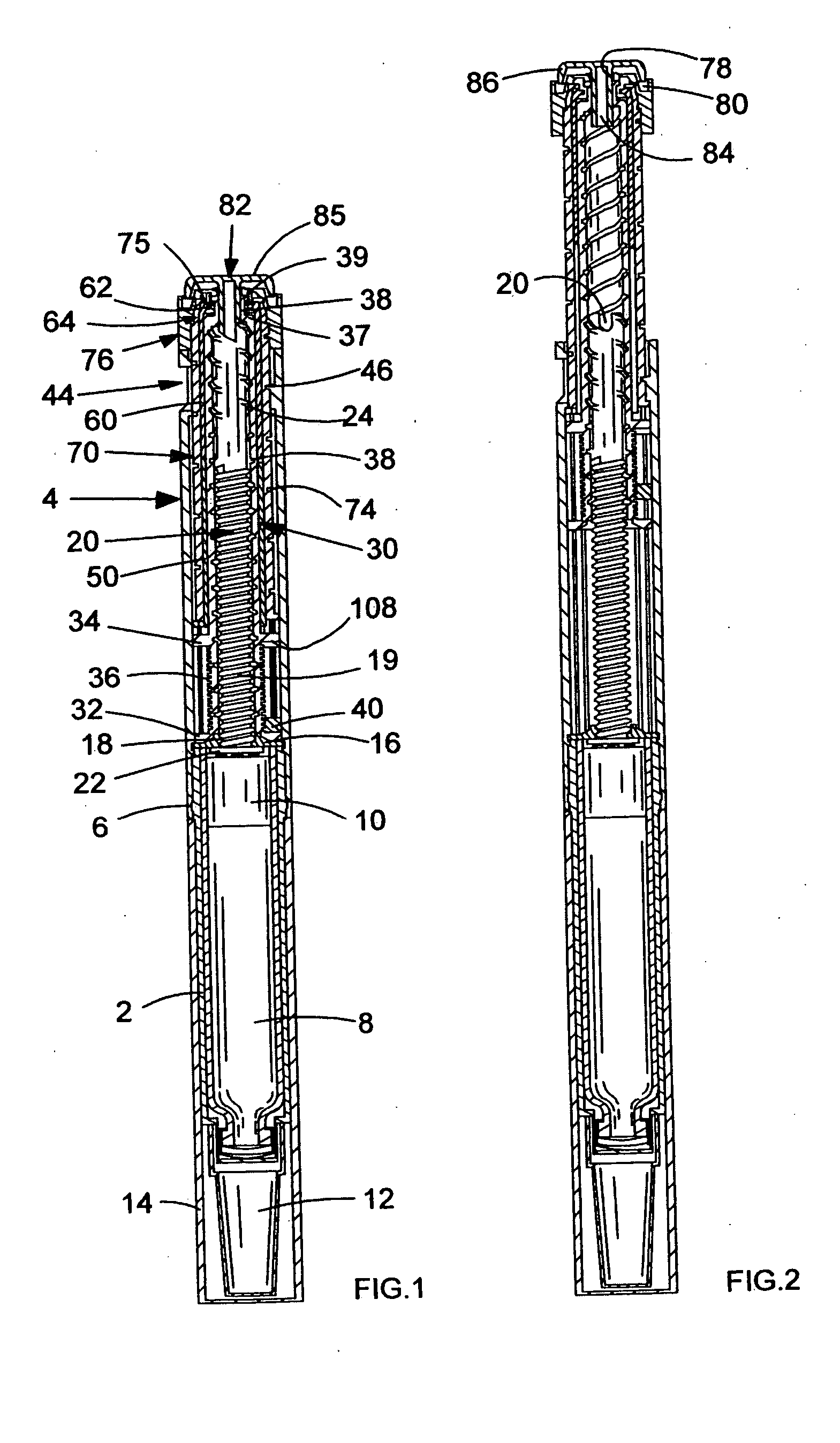
FIG. 1 shows a sectional view of the drug delivery device in accordance with the present invention in a first, cartridge full, position;

FIG. 2 shows a sectional view of the drug delivery device of FIG. 1 in a second, maximum first dose dialed, position;

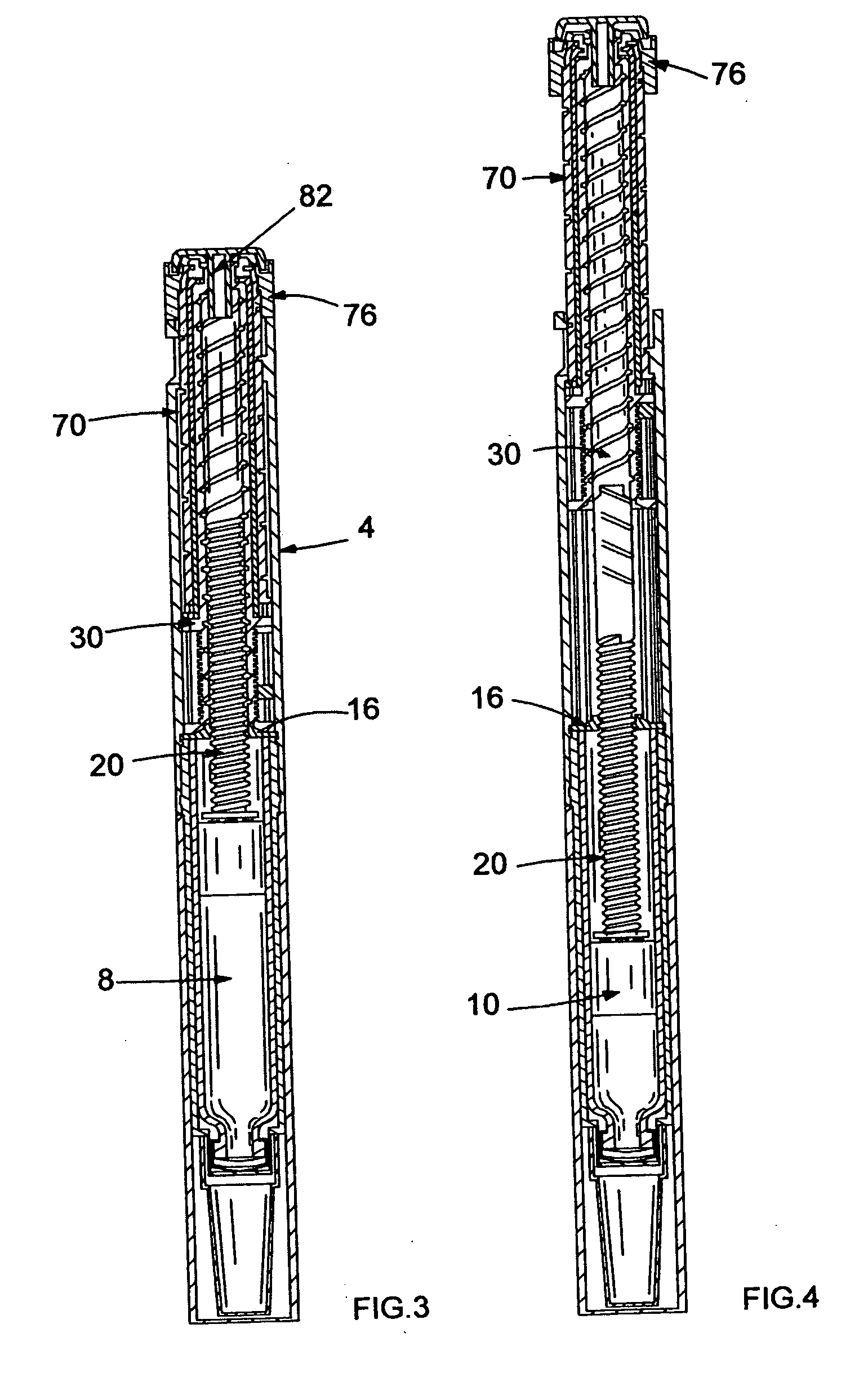
FIG. 3 shows a sectional view of the drug delivery device of FIG. 1 in a third, maximum first dose dispensed, position;

FIG. 4 shows a sectional view of the drug delivery device of FIG. 1 in a fourth, final dose dialed, position;

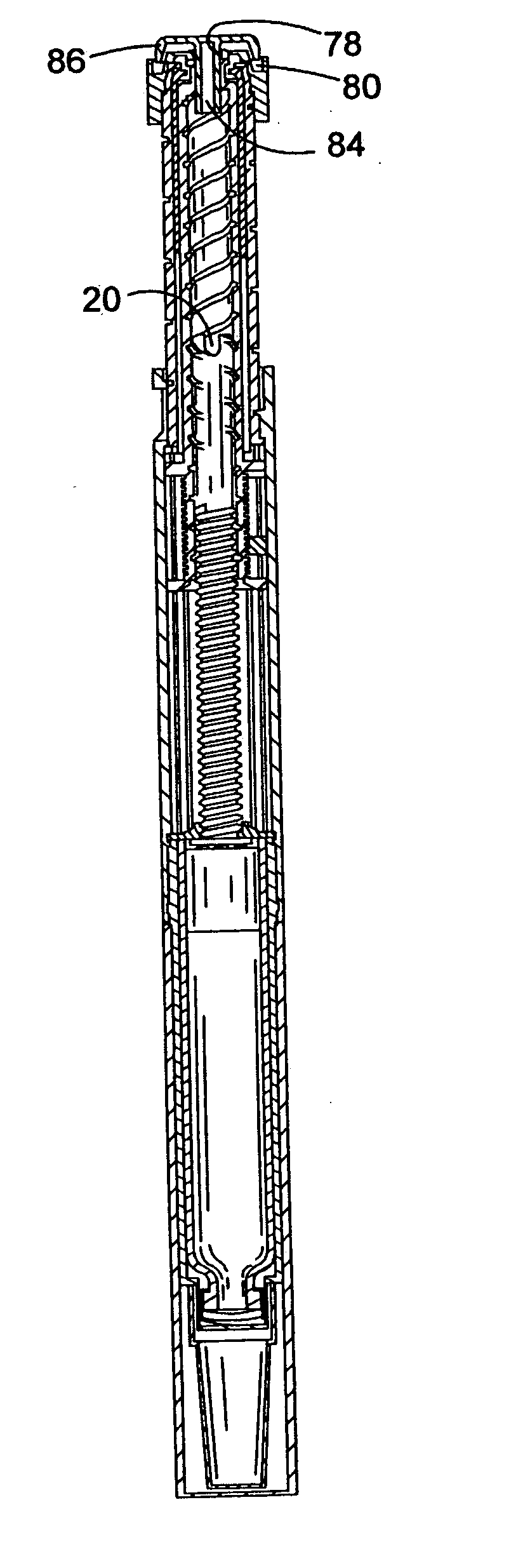
FIG. 5 shows a sectional view of the drug delivery device of FIG. 1 in a fifth, final dose dispensed, position;

FIG. 6 shows a cut-away view of a first detail of the drug delivery device of FIG. 1;

FIG. 7 shows a partially cut-away view of a second detail of the drug delivery device of FIG. 1;

FIG. 8 shows a partially cut-away view of a third detail of the drug delivery device of FIG. 1;

FIG. 9 shows the relative movement of parts of the drug delivery device shown in FIG. 1 during dialing up of a dose;

FIG. ...

second embodiment

FIG. 17 shows a sectional view of the drive mechanism according to instant invention in a first, cartridge full, position.

third embodiment

FIG. 18 shows a sectional side view of the drug delivery device in accordance with the present invention in a first, cartridge full, position;

FIG. 19 shows a sectional side view of the drug delivery device of FIG. 18 in a second, maximum first dose dialed, position;

FIG. 20 shows a sectional side view of the drug delivery device of FIG. 18 in a third, maximum first dose dispensed, position;

FIG. 21 shows a sectional side view of the drug delivery device of FIG. 18 in a fourth, final dose dialed, position;

FIG. 22 shows a sectional side view of the drug delivery device of FIG. 18 in a fifth, final dose dispensed, position;

FIG. 23 shows a fragment of the drug delivery device of FIG. 18 in a larger scale and

FIG. 24 shows a further fragment of the drug delivery device of FIG. 18 in a larger scale.

DETAILED DESCRIPTION OF THE EMBODIMENTS


PUM


Abstract

A drive mechanism suitable for use in drug delivery devices is disclosed. The drive mechanism may be used with injector-type drug delivery devices, such as those permitting a user to set the delivery dose. The drive mechanism may include a housing, a dose dial sleeve, and a drive sleeve. A clutch is configured to permit rotation of the drive sleeve and the dose dial sleeve with respect to the housing when the dose dial sleeve and drive sleeve are coupled through the clutch. Conversely, when the dose dial sleeve and drive sleeve are in a de-coupled state, rotation of the dose dial sleeve with respect to the housing is permitted and rotation of the drive sleeve with respect to the housing is prevented. In the de-coupled state, axial movement of the drive sleeve transfers force in a longitudinal direction for actuation of a drug delivery device.

Description

THE TECHNICAL FIELD OF THE INVENTION The present invention relates to drive mechanisms suitable for use in drug delivery devices, in particular pen-type injectors, having dosage setting means, enabling the administration of medicinal products from a multi-dose cartridge. In particular, the X present invention relates to such drug delivery devices where a user may set the dose. DESCRIPTION OF RELATED ART Such drug delivery devices have application where regular injection by persons without formal medical training occurs, i.e., patients. This is increasingly common amongst those having diabetes where self-treatment enables such persons to conduct effective management of their diabetes. These circumstances set a number of requirements for drug delivery devices of this kind. The device must be robust in construction, yet easy to use in terms of the manipulation of the parts, understanding by a user of its operation and the delivery of the required dose of medicament. Dose setting mus...

Claims


Application Information

Patent Timeline
IPC IPC(8): A61M5/24A61M5/315
CPCA61M5/24A61M5/31535A61M5/31541A61M5/31551A61M5/3156A61M5/31575A61M5/31536A61M2005/2407A61M2205/581A61M2205/582A61M5/31533A61M5/31578A61M5/31565A61M5/31585A61M5/315A61M5/31546A61M5/31528A61M5/31563A61M5/31568A61M5/3157A61M5/31593A61M5/32A61M2005/3126
Inventor VEASEY, ROBERT FREDERICKPERKINS, ROBERTPLUMPTRE, DAVID AUBREY
Owner SANOFI AVENTIS DEUT GMBH
Why Eureka
Try Eureka