Hydrodynamic suture passer

a technology of suture passer and hydrodynamic force, which is applied in the field of surgical instruments, can solve the problems of unable to pass more flexible sutures through the tissue of devices, and unable to achieve the effects of reducing scarring and scarring, and reducing the recovery time and scarring common to such traditional surgery

Inactive Publication Date: 2005-02-10
KIM ANDREW C
View PDF26 Cites 28 Cited by
  • Summary
  • Abstract
  • Description
  • Claims
  • Application Information

AI Technical Summary

Problems solved by technology

Recently developed arthroscopic, endoscopic, and laparoscopic surgical techniques have reduced the pain and discomfort normally experienced by patients undergoing traditional “open” surgery and decreases the recovery time and scarring common to such traditional surgery.
Due to these smaller incisions, the suturing of tissue under the constraints of arthroscopic, endoscopic, or laparoscopic surgery, or any other form of non-open surgery, is difficult with the tools and instruments presently available.
While many instruments have been proposed to solve this problem in the past, such instruments have been found to possess a number of drawbacks.
These devices cannot pass more flexible, braided sutures through the tissue.
However, a device with a closed eyelet provides for difficulty in removing the suture from the eyelet.
However, the notch comprises an exposed surface which can catch on tissue, making passage through the tissue difficult.
However, the use of these instruments has the disadvantage that the suture material must be grasped by an instrument not useful in arthroscopic surgery.
The instruments are of a structural design that is not practical in arthroscopic surgery.
The structure is such that it does not permit the instrument to be used in arthroscopic surgery.
In addition to their inconvenience in use in arthroscopic surgery, these prior art devices present other drawbacks as well.
Soft braided sutures are not typically suited to being pushed from a proximal end to a distal end of a hollow needle.
The presently known suturing instruments and methods, then, are of limited effectiveness for use in closely confined spaces such as sites of arthroscopic surgery.

Method used


Image

  • Hydrodynamic suture passer
  • Hydrodynamic suture passer
  • Hydrodynamic suture passer

Examples


Embodiment Construction

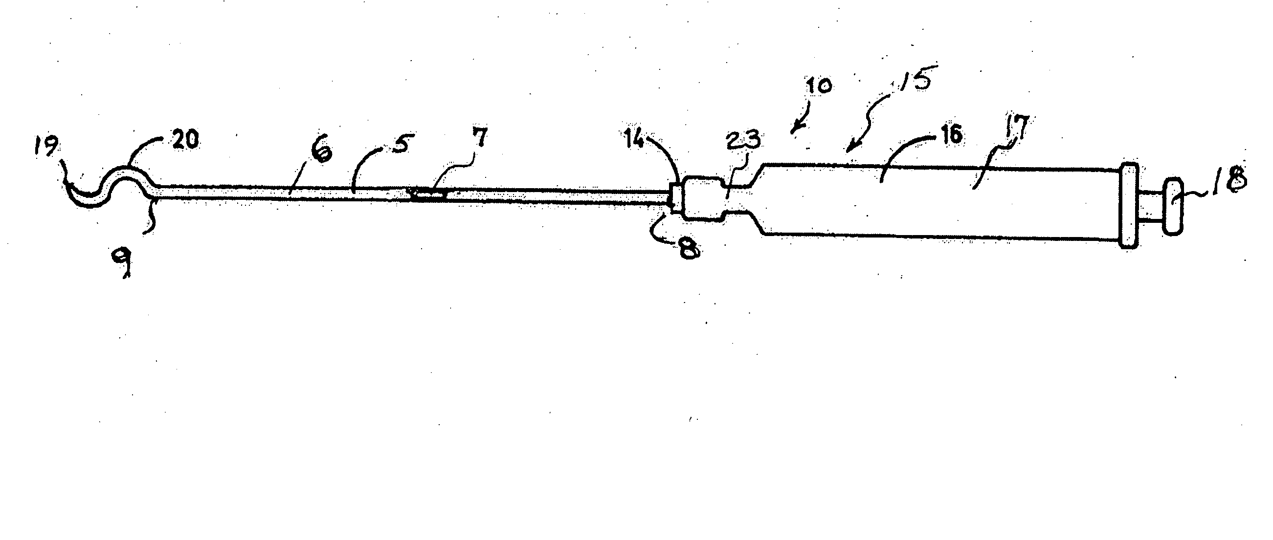
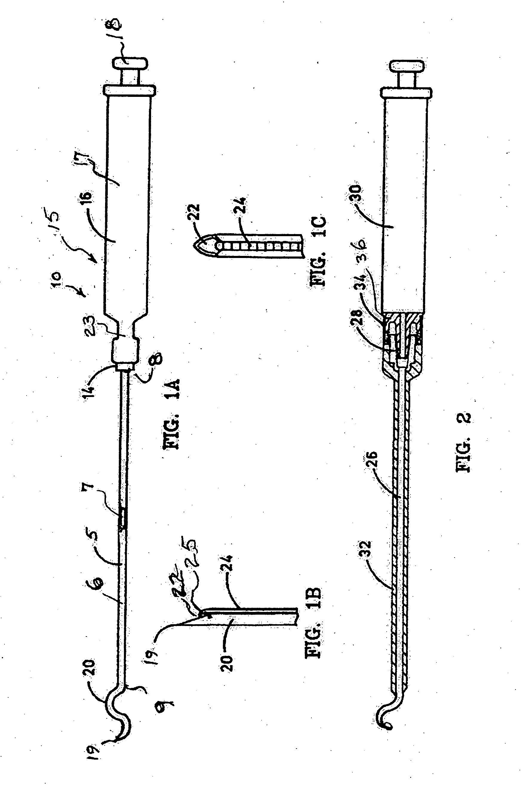
[0036] Referring to the drawings and particularly to FIGS. 1A-1C, a suturing instrument in the form of a special needle and syringe assembly is illustrated and designated generally by the numeral 10. The needle 5 is selected or formed as a cannula 6 with a lumen 7 of sufficient size to receive a desired, or predetermined, size suture. The desired size is generally selected by a surgeon in accordance with the type of surgery to be performed. The needle 5 has a proximal end 8 and a distal end 9. Characterization of one end or the other of the needle 5 is arbitrary. For purposes of the present description, the proximal end is selected to be the end closer to the hand of a surgeon using the instrument 10.

[0037] The proximal end 8 is received in a luer lock fitting 14 of a suction device 15. A preferred form of suction device 15 is a syringe 16 having a syringe barrel 17 and a plunger 18. The syringe barrel 17 may be of a conventional construction, i.e., have a circular cross section. A...


PUM


Abstract

A hydrodynamic suturing instrument, comprising an elongated cannulated suturing needle having a distal end configured to carry a suture through tissue and a proximal end adapted to connect to a syringe barrel and a lumen extending form said proximal end to an opening at the distal end for having a size for the passage of a suture, the opening at the distal end configured to receive a suture extending from the lumen along an outer surface of the needle wherein a sharp point extends forward of the suture. A companion instrument includes forceps having a distal end with jaws and a proximal end with a cannula extending from the proximal end to the distal end for passage of the needle, and the jaws having an opening enabling passage of the needle through tissue grasped in the jaws.

Description

CROSS REFERENCE TO RELATED APPLICATIONS [0001] This application is a continuation-in-part of U.S. patent application Ser. No. 10 / 614,563 filed Jul. 7, 2003, from which priority is claimed under 35 U.S.C. § 120 and which is incorporated herein by reference in its entirety.FIELD OF THE INVENTION [0002] The present subject matter relates to surgical instruments and pertains particularly to an apparatus and method for passing sutures through tissue. BACKGROUND OF THE INVENTION [0003] Recently developed arthroscopic, endoscopic, and laparoscopic surgical techniques have reduced the pain and discomfort normally experienced by patients undergoing traditional “open” surgery and decreases the recovery time and scarring common to such traditional surgery. These techniques are commonly performed in confined spaces, wherein one or more tubes may be inserted in the patient, and surgical instruments and materials are moved in to the surgery site through the tube or tubes. Accordingly, these surgi...

Claims


Application Information

Patent Timeline
Patent Type & Authority Applications(United States)
IPC IPC(8): A61B17/00A61B17/04A61B17/06A61B17/28
CPCA61B17/0469A61B17/0482A61B17/29A61B2017/06171A61B2017/00353A61B2017/06076A61B17/295
Inventor KIM, ANDREW C.
Owner KIM ANDREW C
Why Eureka
Try Eureka