Apparatus and method for manufacture and use of composite fiber components

a technology of composite fiber and components, applied in the direction of mechanical control devices, document inserters, tires, etc., can solve the problems of limited applicability of other known techniques, limited design control of many mechanical material properties, and known apparatuses and methods

Active Publication Date: 2005-02-17
LIGNUM VITAE
View PDF6 Cites 49 Cited by
  • Summary
  • Abstract
  • Description
  • Claims
  • Application Information

AI Technical Summary

Benefits of technology

[0010] In some embodiments, a fiber source may provide a feed of fiber. A fiber source may also include one or more fiber supplies. A fiber supply may comprise a fiber spool, a fiber creel, a vapor deposition chamber, or other type of fiber supply. According to one embodiment, a fiber may be fed under tension to-provide a pre-stress to the fiber. The pre-stress may enhance one or more features of the fiber prior to being layed-up. As an example, the pre-stress may strengthen the fiber, or enhance another feature of the fiber.
[0030] In some embodiments of the invention, the fiber lay-up apparatus may be used to manufacture components of a particular system, such as a truss system, or other system. The truss system, for instance, may provide a low weight, high strength truss system for use in a shelter, a gantry crane, a bridge, or in any other structure that includes a truss system. The truss system may further provide a high strength by resolving all external forces internally, thereby including no external nodes.

Problems solved by technology

Many drawbacks exist with the known apparatus and methods.
However, these and other known techniques may be limited in their range of applicability because of limitations in at least one material property capability.
For example, spray lay-up provides for speedy manufacture at a reasonable price, but may only be capable of incorporating short fibers into a manufactured component, which may limit design control over many mechanical material properties.
Similarly, pultrusion manufacture is economical and may provide good control over material properties of a manufactured component, yet it is often limited by the component geometries that may be produced.

Method used


Image

  • Apparatus and method for manufacture and use of composite fiber components
  • Apparatus and method for manufacture and use of composite fiber components
  • Apparatus and method for manufacture and use of composite fiber components

Examples


Embodiment Construction

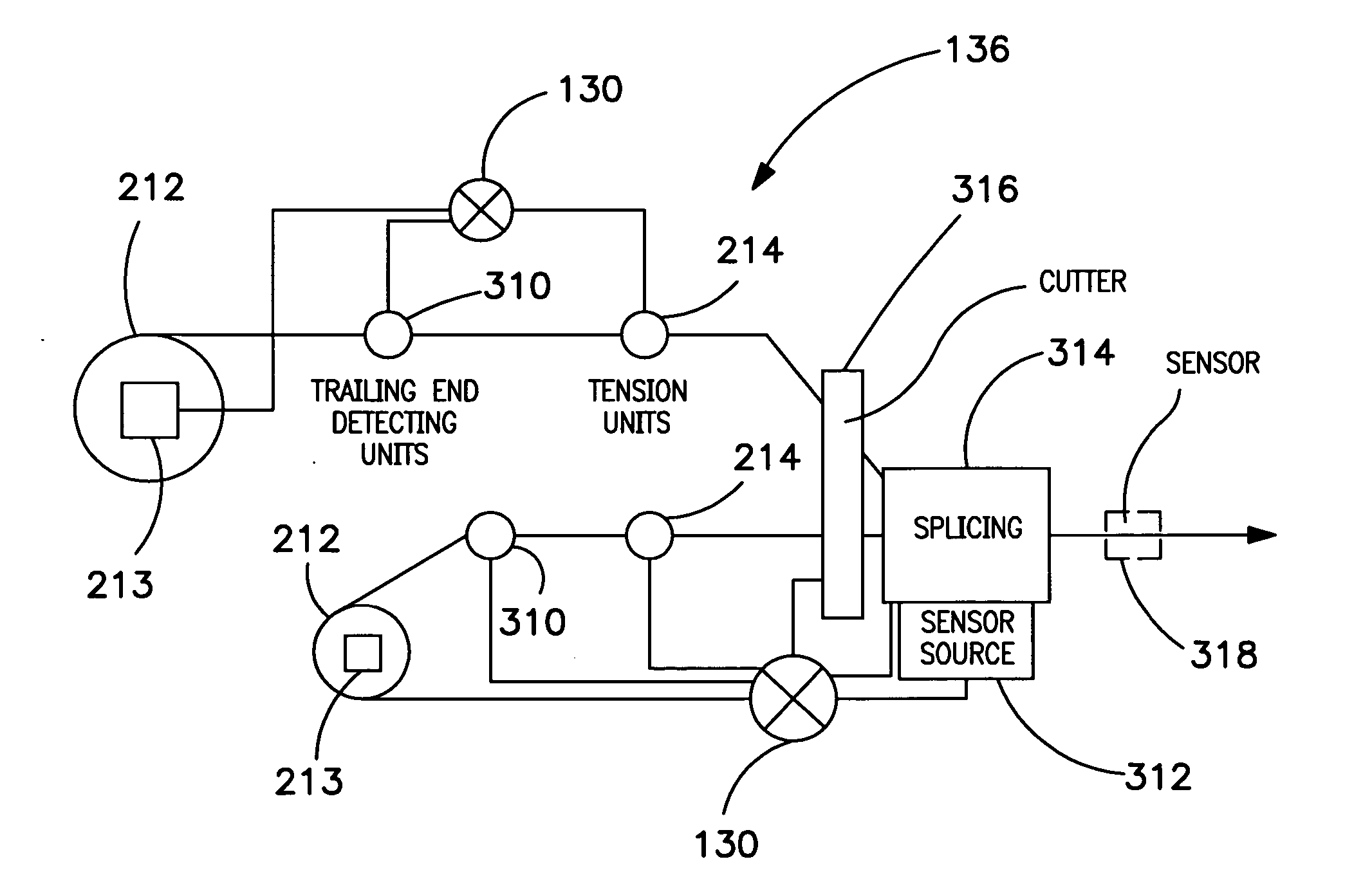
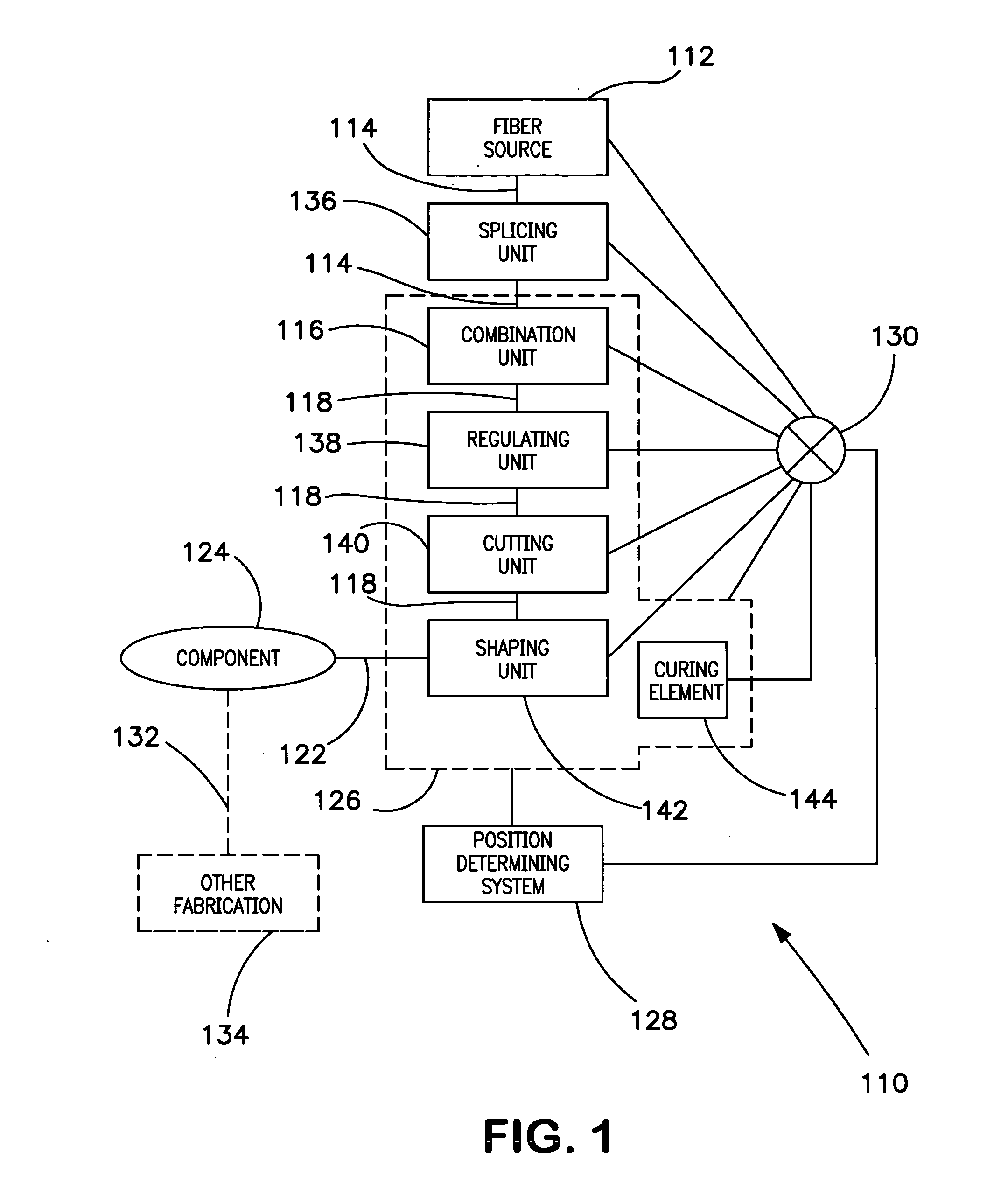
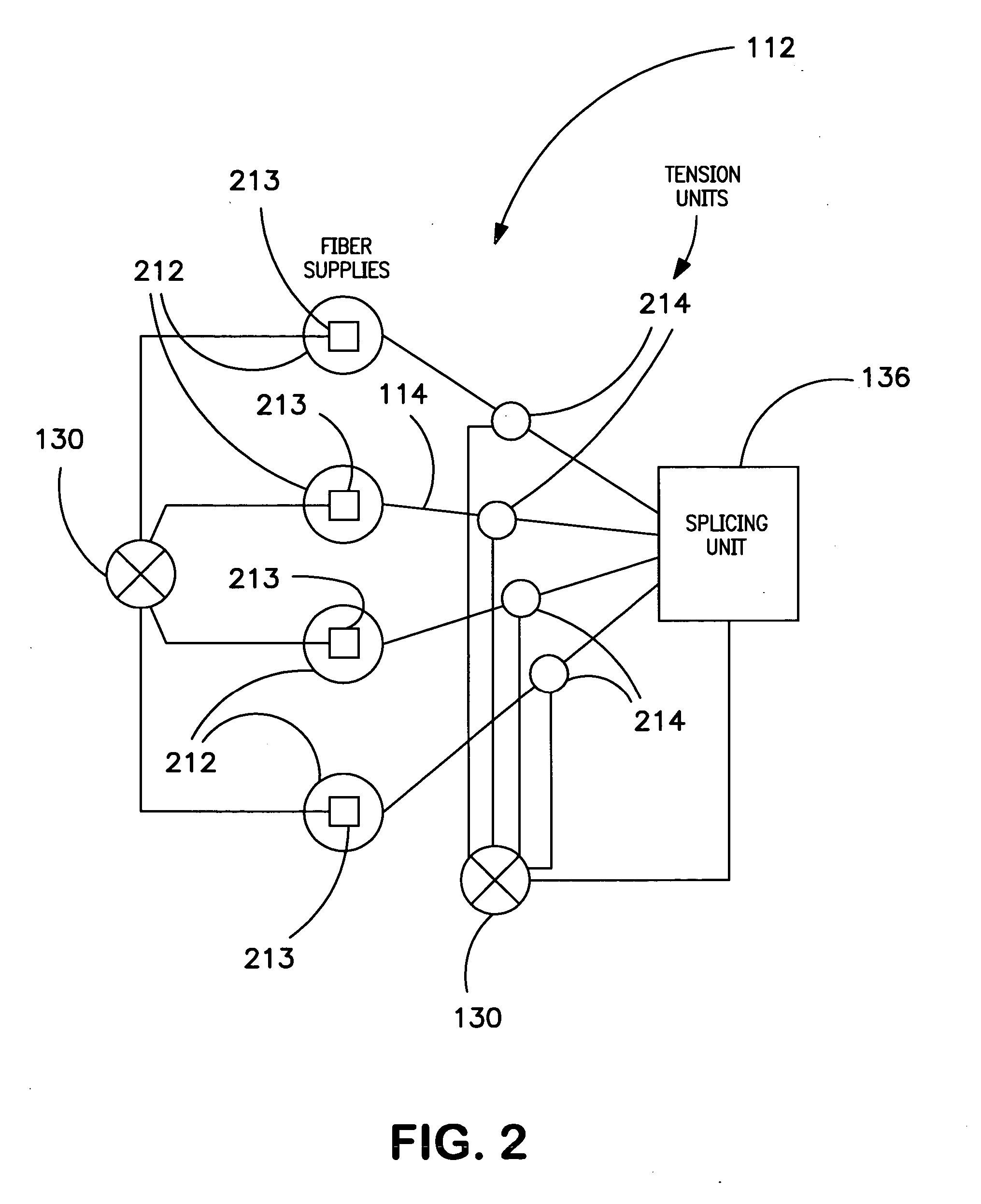
[0066] Various aspects of the invention relate to an apparatus and method for performing automated fiber lay-up. FIG. 1 illustrates an embodiment of a fiber lay-up apparatus 110. Fiber lay-up apparatus 110 may comprise a fiber source 112 that may release or feed one or more dry fibers 114 under tension. Fiber 114 may be released under tension to provide a pre-stress to the fiber 114. Fiber 114 may further be fed through a splicing unit 136 that may be employed to splice one fiber to another for various purposes.

[0067] A combination unit 116 may be provided to combine fiber 114 with one or more matrices to create a fiber 118 combined with the matrix. The matrix material may enable the one-dimensional fiber 118 to be used in three-dimensional fabrication. The fiber 118 and matrix material may be combined under pressure, which may be pulsed, for example, to reduce friction, provide a motive force to fiber 118, enhance control over combination, or provide other benefits.

[0068] A regul...


PUM

PropertyMeasurementUnit
motive forceaaaaaaaaaa
lengthaaaaaaaaaa
non-contact motive forceaaaaaaaaaa

Abstract

A fiber lay-up apparatus and method includes one or more fiber sources from at least one fiber supply wherein a fiber may be fed under tension to provide a pre-stress to the fiber. The fiber lay-up apparatus may include a resin impregnator for impregnating a fiber with a resin. The fiber may be impregnated under pressure to reduce friction, to provide a motive force to move the fiber through the impregnator, or to enhance control over impregnation. The fiber may be shaped by a fiber shaping unit including one or more active or passive shaping members that provide enhanced control over the shape and placement of the fiber as the fiber leaves the fiber lay-up apparatus. A cutting element for cutting a fiber as it is being layed-up may be positioned proximal to the one or more shaping members, and may enable the fiber lay-up apparatus to end the lay-up of one fiber (or set of fibers) and begin the lay-up of a new fiber (or set of fibers) without delay. A UV or other curing element may be provided downstream from the cutting element. A splicing unit may be employed to detect when a fiber supply is exhausted, and may splice a trailing end of an exhausted fiber supply to a leading end of a new fiber supply to provide a continuous (or substantially continuous) fiber feed. The splicing unit may also splice at least one sensor into a fiber being fed from the at least one fiber supply to provide information about the fiber either before, during, or after the fiber is layed-up.

Description

CROSS-REFERENCE TO RELATED APPLICATIONS [0001] This Application claims priority to the following U.S. Provisional Patent Applications, each of which are incorporated herein by reference in their entirety: U.S. Provisional Patent Application Ser. No. (Attorney Docket No. TT2), filed Feb. 25, 2004, by inventor Michael Bonaventura Warek, entitled “Tension Truss, oblique prestressed structural elements;” U.S. Provisional Patent Application Ser. No. 60 / 504,387, filed Sep. 20, 2003; and U.S. Provisional Patent Application Ser. No. 60 / 464,168, filed Apr. 21, 2003.FIELD OF THE INVENTION [0002] The invention relates to methods and apparatus for manufacture and use of composite fiber components. BACKGROUND OF THE INVENTION [0003] Apparatus and methods for manufacture and use of composite fibers in general are known. Many drawbacks exist with the known apparatus and methods. [0004] In recent years, many industries including, but not limited to, the aerospace, automotive, marine, wind energy sy...

Claims


Application Information

Patent Timeline
Patent Type & Authority Applications(United States)
IPC IPC(8): B29C70/38B29C70/50B29C70/54
CPCB29C70/202B29C70/28B29C70/32B29C70/382B29C70/46B29C70/50Y10T428/2913B29C70/527B29C70/528B29C70/54B29C70/545B29C70/56Y10T156/1352B29C70/525
Inventor WAREK, MICHAEL BONAVENTURA
Owner LIGNUM VITAE
Why Eureka
Try Eureka