

Cartridge with slanted memory chip and conforming wall
- Summary
- Abstract
- Description
- Claims
- Application Information
AI Technical Summary
Benefits of technology
Problems solved by technology
Method used
Image

Examples
Embodiment Construction
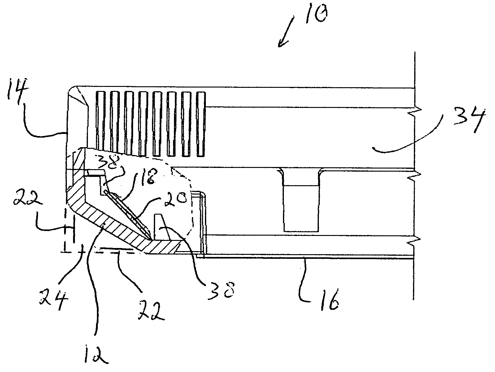
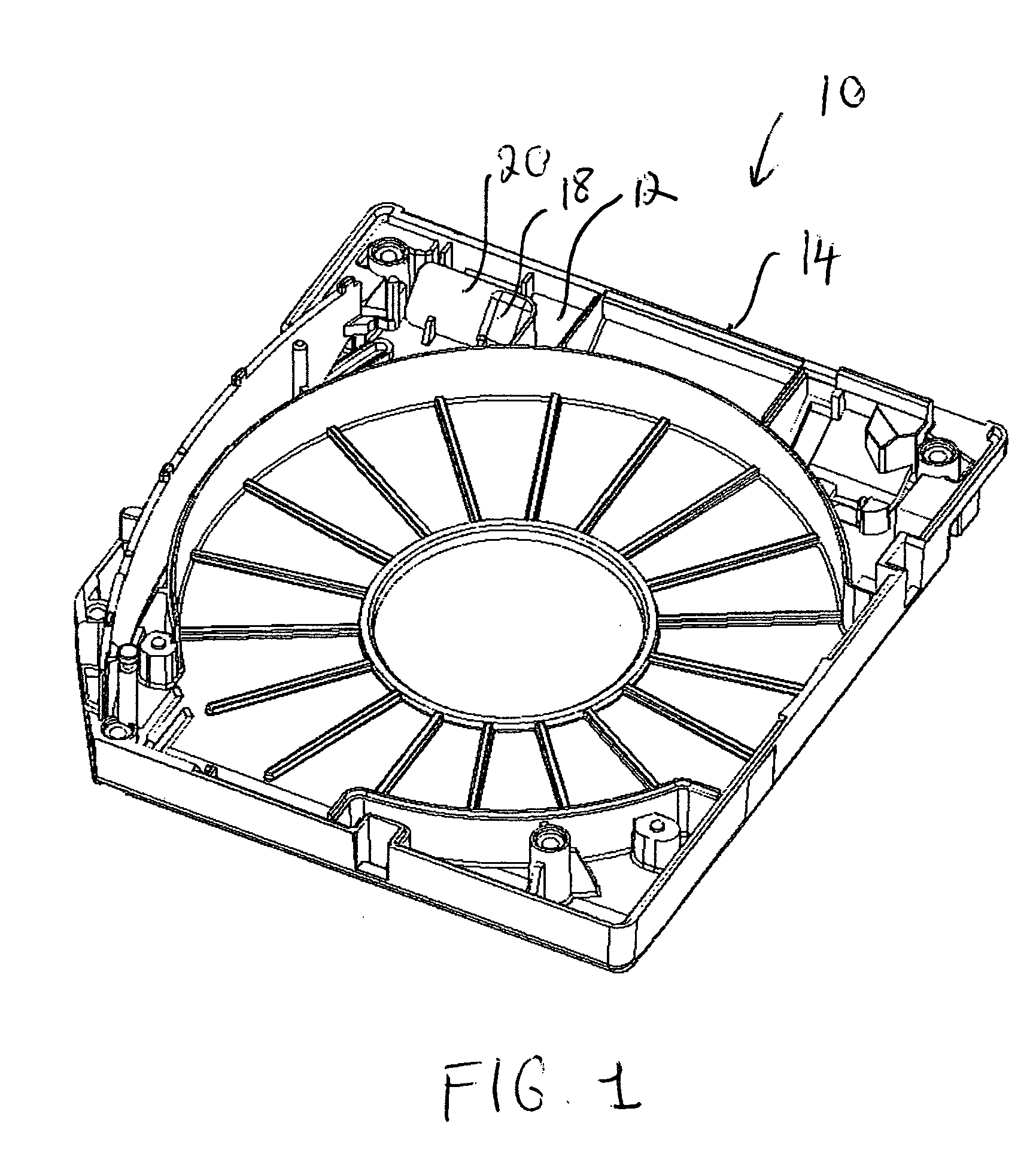
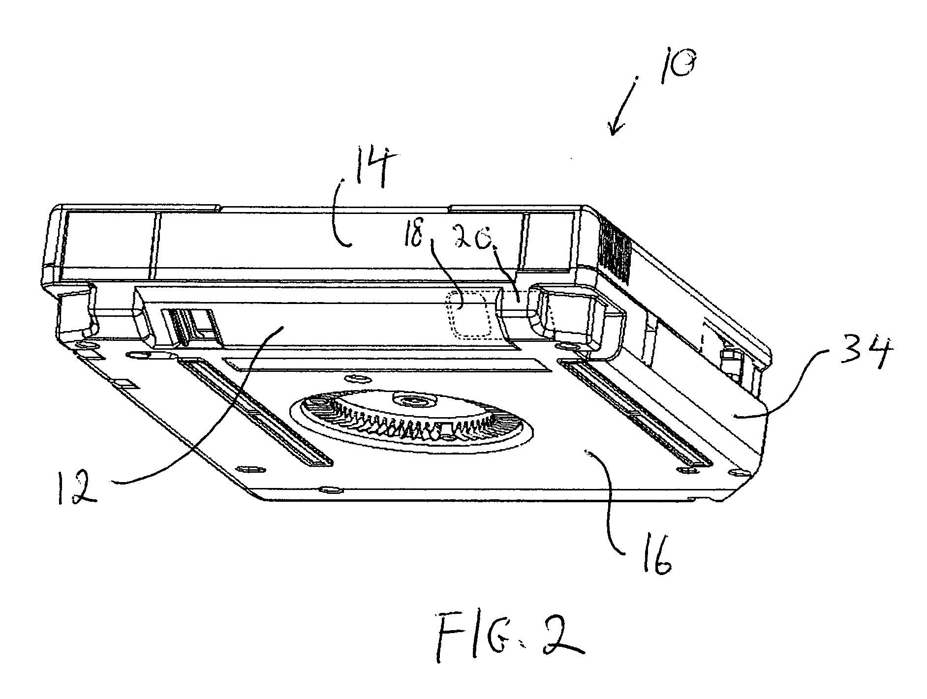
[0019] The heart of this invention lies in the recognition that the elimination of a corner section from two adjacent walls in the casing of a conventional tape cartridge would reduce the space occupied by the cartridge when placed in operation for RF data transmission. Accordingly, the freed space advantageously enables the placement of the antennas of one or more external reading devices in closer proximity than heretofore possible to the antenna of the memory chip mounted inside the cartridge.
[0020] For the purposes of this disclosure, the terms rear and front are used throughout in connection with the structure of a typical tape cartridge described herein to refer to the side facing the gripper arms of an automated picker and the side facing the drive during use, respectively. Left and right refer to the cartridge lateral sides as they appear viewing the cartridge from its front side. The terms bottom and top are used with reference to the side of the cartridge that contains th...
PUM
 Abstract
Description
Claims
Application Information