Optical Data Transmission System

a data transmission system and optical data technology, applied in the direction of transmission, electromagnetic transmission, bus-type electromagnetic networks, etc., can solve the problems of inability to check the performance of the data, errors in the readout, and inability to perform diagnostic methods or load software, etc., to achieve the effect of improving the data transmission

Active Publication Date: 2013-01-10
AIRBUS DEFENCE & SPACE
View PDF19 Cites 0 Cited by
  • Summary
  • Abstract
  • Description
  • Claims
  • Application Information

AI Technical Summary

Benefits of technology

[0006]Exemplary embodiments of the present invention provide an improved data transmission between a device and an optical maintenance port.

Problems solved by technology

However, errors may occur in readout, performing the diagnostic method, or loading software.
It is impossible here to check the performance while performing the diagnostic procedure as part of maintenance and to forward any errors detected to the user.
These are extremely impractical with regard to their dimensions, lengthening the optical path for the signals, significantly increasing damping and causing substantial costs for the manufacturer.
This approach from the state of the art also leads to inadequacies when there are great temperature differences.

Method used


Image

  • Optical Data Transmission System
  • Optical Data Transmission System
  • Optical Data Transmission System

Examples


Embodiment Construction

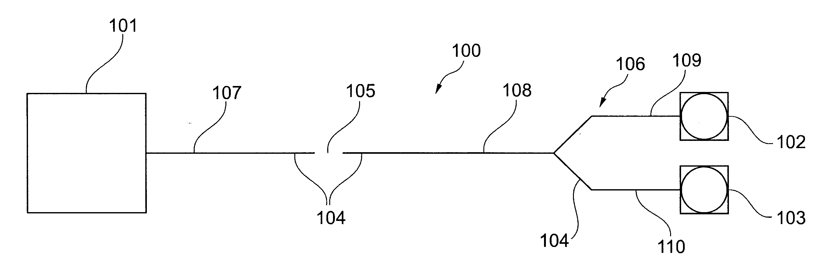
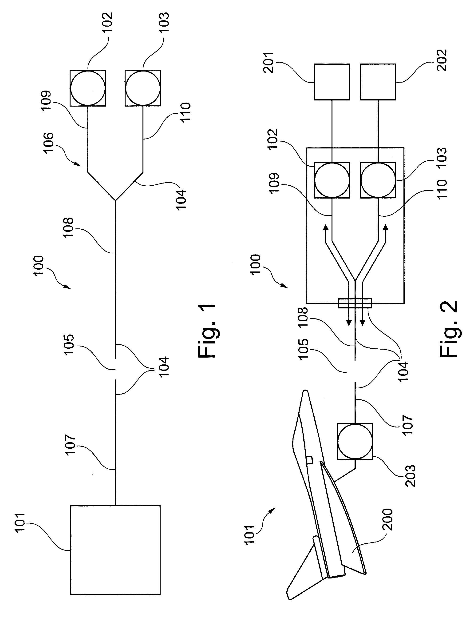
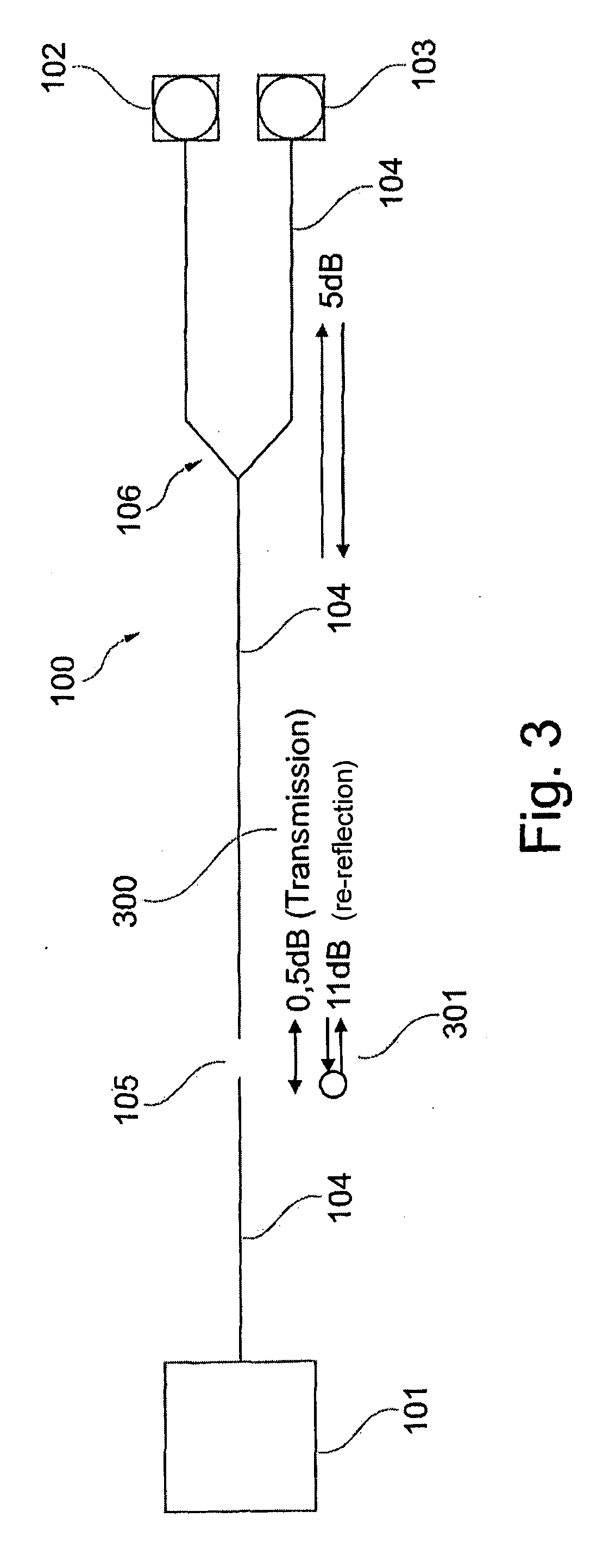
[0063]FIG. 1 shows an optical data transmission system 100 having a device 101, a first optical maintenance port 102 and a second optical maintenance port 103. In addition, the optical data transmission system has a solid-state bound data line 104 for transmitting data by means of electromagnetic energy between the device 101 and the first optical maintenance port 102 and the second optical maintenance port 103. This solid-state bound data line is embodied here as a fiber optic data line. The fiber optic data line 104 is interrupted by the gap 105 between the device on the one hand and the first and the second optical maintenance ports on the other hand. In the exemplary embodiment shown here, the gap, shown here as an interruption 105, is embodied with air as the material in the gap and zirconia as the spacer sleeve between the glass fiber segments of the data line. The spacer may be embodied in the form of a clamping sleeve or a wafer or a spacer ring. This can be derived from the...


PUM


Abstract

A data transmission between a device and a first and a second optical maintenance port involves a transmission reflector in the form of a solid-state bound data line having a gap and a Y coupler. This allows recording of the communication between the device to be read out and the first optical maintenance port in real time by means of the second optical port. Likewise, communication by means of electromagnetic energy is possible between the first and the second optical maintenance ports.

Description

CROSS-REFERENCE TO RELATED APPLICATIONS[0001]The present application claims priority under 35 U.S.C. §119 to German Application No. 10 2011 106 783.7, filed Jul. 6, 2011, the entire disclosure of which is herein expressly incorporated by reference.FIELD OF THE INVENTION[0002]Exemplary embodiments of the present invention relate to the optical data transmission and / or optical readout of data of a device. In particular, exemplary embodiments of the present invention related to an optical data transmission system, an aircraft having an optical data transmission system, the use of an optical data transmission system in an aircraft and a method for readout of data of a device.TECHNOLOGICAL BACKGROUND[0003]Complex technical devices today usually have their own internal software. Such devices can generate data that is of interest for the user or for a method for checking the device. Such data may then be read out via optical ports, for example, and forwarded to diagnostic devices. Especial...

Claims


Application Information

Patent Timeline
Patent Type & Authority Applications(United States)
IPC IPC(8): H04B10/04H04B10/08
CPCH04B10/278G02B6/2817
Inventor PLANKL, HELMUT
Owner AIRBUS DEFENCE & SPACE
Why Eureka
Try Eureka