Palm mechanism for robot hand

a robot hand and mechanism technology, applied in the direction of manipulators, load-engaging elements, gripping heads, etc., can solve the problems and achieve the effect of difficult to perform quick and accurate operations

Active Publication Date: 2005-02-24
HARMONIC DRIVE SYST IND CO LTD
View PDF7 Cites 19 Cited by
  • Summary
  • Abstract
  • Description
  • Claims
  • Application Information

AI Technical Summary

Benefits of technology

[0005] It would be convenient in this case if the one finger positioned opposite the four fingers were configured so as to be capable of turning along the palm because operations such as gripping objects could be performed in a greater variety of patterns due to the fact that the relative position of the one finger would be freely variable with respect to the four fingers. A mechanism comprising a servo actuator, a transmitting mechanism comprising a combination of pinions and internal gears, or a transmitting mechanism that makes use of a belt and rope may be considered as a mechanism for turning the finger. However, all of these have complex and weighty structures and make it difficult to perform quick and accurate operations.
[0006] An object of the present invention is to provide a palm mechanism for a robot hand that is capable of performing a variety of hand operations by which the finger can be moved at high speed in accordance with an objective and be deployed in a predetermined position in conjunction with rapid and accurate finger operation.
[0029] To allow a bevel gear to move without backlash, a spring plate is preferably mounted on an external end surface of the bearings in order to restrict the axial bias of the driven-side bevel gear fixed to the joint shaft.

Problems solved by technology

However, all of these have complex and weighty structures and make it difficult to perform quick and accurate operations.

Method used


Image

  • Palm mechanism for robot hand
  • Palm mechanism for robot hand
  • Palm mechanism for robot hand

Examples


Embodiment Construction

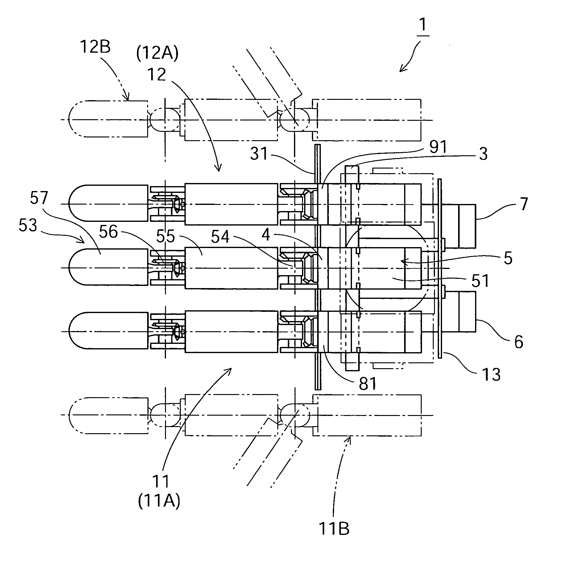
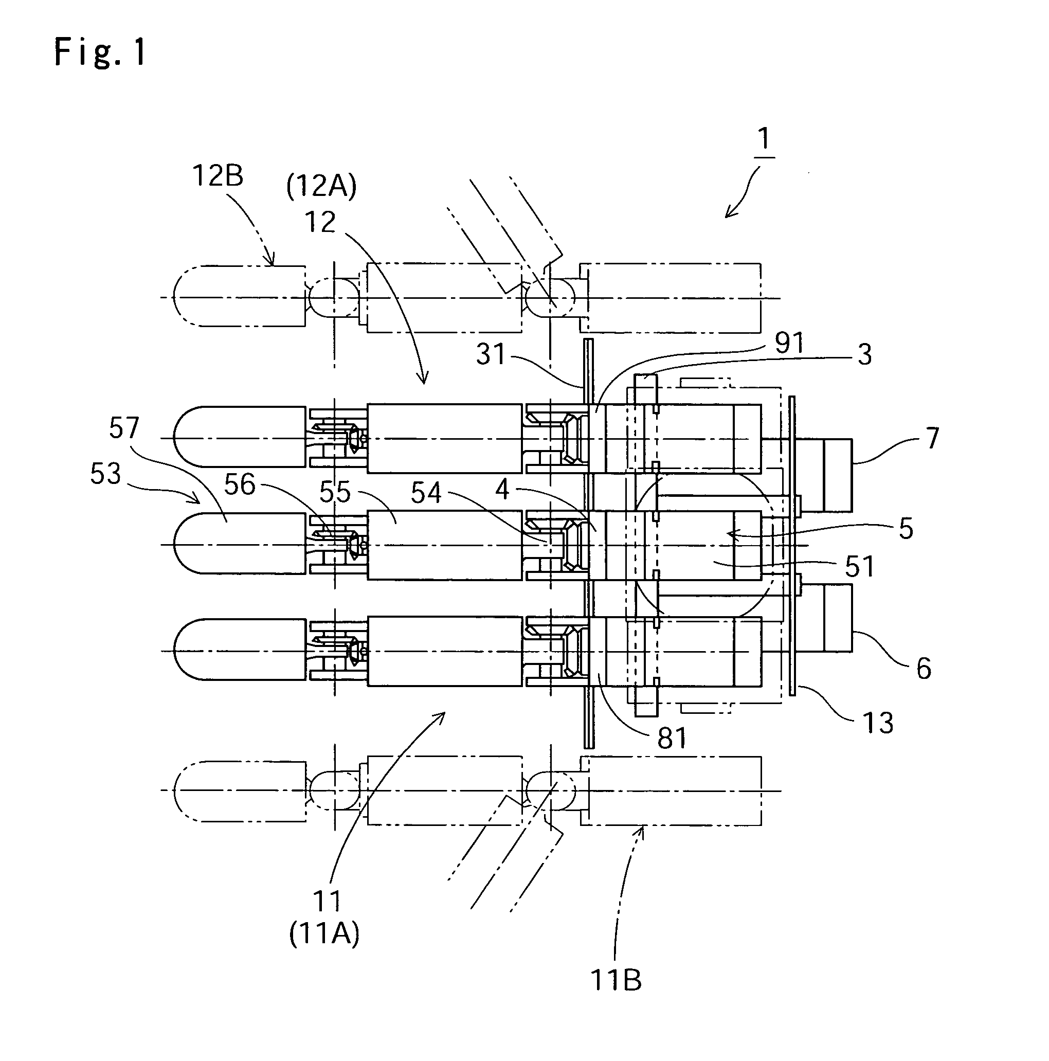
[0051] A palm mechanism for a high-speed robot hand to which the present invention has been applied is described below with reference to the diagrams.

[0052]FIG. 1 is a top view showing a palm mechanism for a high-speed robot hand of the present embodiment, FIG. 2 is a cross-sectional view thereof, and FIG. 3 is a front view thereof. FIG. 4A is a rear view of the palm mechanism for a high-speed robot hand, and FIG. 4B is a cross-sectional view of the sectioned portion along the line B-B thereof. With reference to these drawings, a palm mechanism 1 for a high-speed robot hand has a vertically positioned rectangular palm plate 3, and three articulated finger units 5, 11, and 12. The articulated finger unit 5 can be controlled to respectively bend to an angle of 90° or a similar angle outward or inward from a linearly extended state, and this bending operation can be performed at high speed and with accuracy. This articulated finger unit 5 is fixed to a center portion of an upper long ...


PUM


Abstract

A palm mechanism for a high-speed robot hand has a fixed-side articulated finger unit that projects forward from an upper side of a vertically positioned palm plate, and moveable-side articulated finger units disposed on both sides thereof. The left and right articulated finger units are capable of turning along two short sides of the rectangular palm plate from upper end positions on the palm mechanism. The articulated finger units are capable of bending up and down about joint portions thereof. A variety of operations, including gripping, picking, and throwing, can be performed rapidly and reliably by controlling relative positions of the three articulated finger units and controlling bending operations of the articulated finger units.

Description

BACKGROUND OF THE INVENTION [0001] 1. Field of the Invention [0002] The present invention relates to a palm mechanism for a robot hand that is capable of accurately catching flying objects and the like at high speeds. [0003] 2. Description of the Related Art [0004] Conventional palm mechanisms for robot hands have, in the case of a palm mechanism composed of a total of five fingers, for example, a structure in which four of the fingers are fixed in a row on one side of the external periphery of the palm, and the remaining finger is fixed in a location that is 180° on the opposite side of the palm with respect to these four fingers. Most of these palm mechanisms simultaneously bend each of the four fingers positioned on one side of the palm and the one finger positioned on the other side of the palm, and catch objects, pick objects, or perform other simple actions at a speed approximately equivalent to that of a human. SUMMARY OF THE INVENTION [0005] It would be convenient in this ca...

Claims


Application Information

Patent Timeline
Patent Type & Authority Applications(United States)
IPC IPC(8): B25J15/08B25J15/00
CPCB25J15/0009
Inventor KAMEDA, HIROSHIKOYAMA, JUNJIMORIMOTO, TEIZOSASAHARA, MASAKATSU
Owner HARMONIC DRIVE SYST IND CO LTD
Why Eureka
Try Eureka