Edge detecting apparatus and method, and image size enlarging and reducing apparatus and method

a technology of edge detection and detecting apparatus, applied in image enhancement, image analysis, instruments, etc., can solve the problems of blurred edge area, inability to judge, blurred edge area, etc., and achieve the effect of less blurring of edge and simple operation

Inactive Publication Date: 2005-02-24
FUJIFILM CORP
View PDF11 Cites 44 Cited by
  • Summary
  • Abstract
  • Description
  • Claims
  • Application Information

AI Technical Summary

Benefits of technology

[0017] Another object of the present invention is to provide an image size enlarging and reducing apparatus, wherein an image size enlargement or reduction processing is capable of being performed quickly such that an edge area in an image may not be blurred.
[0146] The image interpolation apparatus and method in accordance with the present invention may be modified such that the interpolating operation is the operation for: representing the position of each of three pixels, which are located in the vicinity of the new pixel, by the x coordinate and the y coordinate, representing the pixel value of each of the three pixels, which are located in the vicinity of the new pixel, by the z coordinate, setting the plane, which passes through the z coordinates of the pixel values of the three pixels located in the vicinity of the new pixel, and taking the value of the z coordinate, which corresponds to the x and y coordinates of the new pixel, in the thus set plane as the pixel value of the new pixel. With the modifications of the image interpolation apparatus and method in accordance with the present invention, the pixel value of the new pixel is capable of being calculated with the simple operation.

Problems solved by technology

However, in cases where the image size enlargement or reduction processing on the image signal is performed with a single technique alone, the problems occur in that an edge area contained in the image is blurred or becomes shaggy.
However, in cases where the detection of an edge is performed by use of the aforesaid filter having an odd number of the taps, a judgment is capable of being made merely as to whether a pixel of interest itself in an image is or is not a pixel constituting the edge in the image, and a judgment is not capable of being made as to whether an edge in the image is or is not located between pixels.
However, the known techniques described above are utilized as the interpolating operation processes, and therefore the problems still occur in that the edge area is blurred.
As a result, the edge area in the image obtained from the image size enlargement or reduction processing becomes blurred.
Therefore, a long time is required to perform the interpolating operation.
Therefore, the problems occur in that the edge area in the image obtained from the image size enlargement or reduction processing becomes blurred.

Method used


Image

  • Edge detecting apparatus and method, and image size enlarging and reducing apparatus and method
  • Edge detecting apparatus and method, and image size enlarging and reducing apparatus and method
  • Edge detecting apparatus and method, and image size enlarging and reducing apparatus and method

Examples


first embodiment

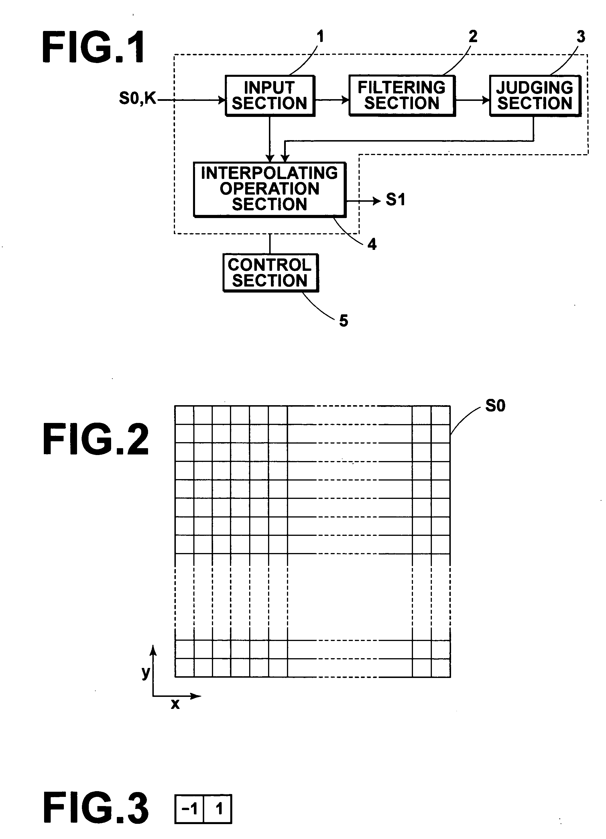
[0187] As illustrated in FIG. 2, the image represented by the image signal S0 is constituted of pixels arrayed in two-dimensional directions. (The image represented by the image signal S0 will hereinbelow be also represented by S0.) In the image size enlarging and reducing apparatus of FIG. 1, in which the edge detecting apparatus in accordance with the present invention is employed, (and in various other embodiments, which will be described later), an x direction and a y direction are defined as illustrated in FIG. 2.

[0188] With respect to each of rows of the pixels in the image S0, which rows extend in the x direction, and each of columns of the pixels in the image S0, which columns extend in the y direction, the filtering section 2 performs filtering processing with a difference filter and on two pixels, which are adjacent to each other and between which a pixel to be interpolated for image size enlargement processing is located. (The pixel to be interpolated for the image size e...

second embodiment

[0207] An image size enlarging and reducing apparatus, in which the edge detecting apparatus in accordance with the present invention is employed, will be described hereinbelow.

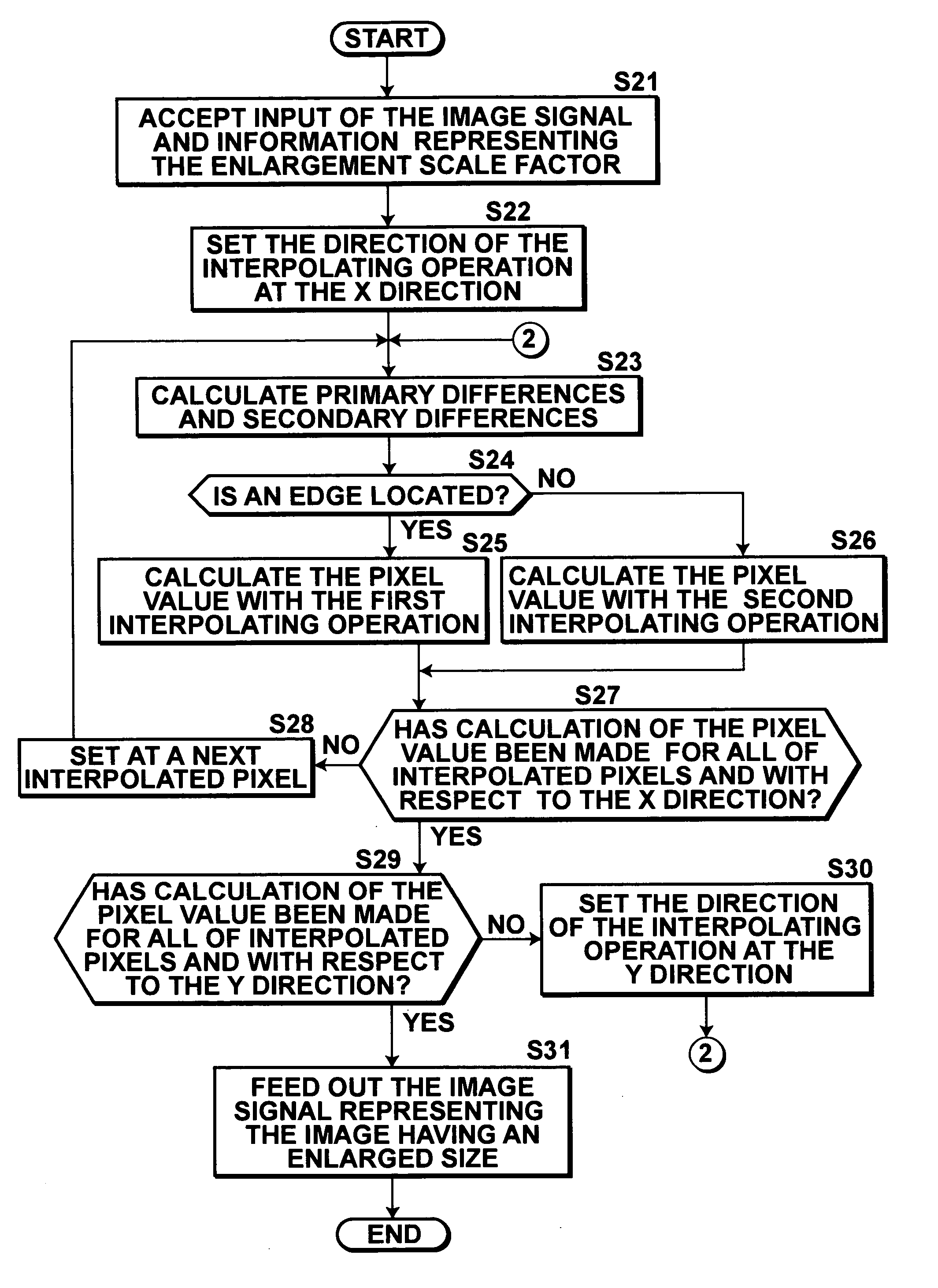
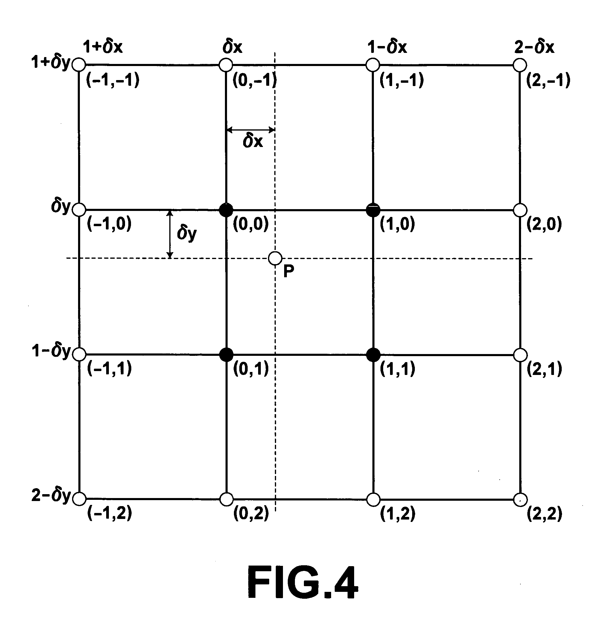
[0208]FIG. 7 is a block diagram showing an image size enlarging and reducing apparatus, in which a second embodiment of the edge detecting apparatus in accordance with the present invention is employed. As illustrated in FIG. 7, the image size enlarging and reducing apparatus, in which the second embodiment of the edge detecting apparatus in accordance with the present invention is employed, comprises an input section 11 for accepting the inputs of the image signal S0 and the information representing the enlargement scale factor K for the image signal S0. The image size enlarging and reducing apparatus also comprises a filtering section 12, a judging section 13, and an interpolating operation section 14 for calculating the pixel value of the interpolated pixel P. The image size enlarging and reducing apparatu...

third embodiment

[0221] An image size enlarging and reducing apparatus, in which the edge detecting apparatus in accordance with the present invention is employed, will be described hereinbelow.

[0222]FIG. 13 is a block diagram showing an image size enlarging and reducing apparatus, in which a third embodiment of the edge detecting apparatus in accordance with the present invention is employed. As illustrated in FIG. 13, the image size enlarging and reducing apparatus, in which the third embodiment of the edge detecting apparatus in accordance with the present invention is employed, comprises an input section 21 for accepting the inputs of the image signal S0 and the information representing the enlargement scale factor K for the image signal S0. The image size enlarging and reducing apparatus also comprises a first filtering section 22A, a second filtering section 22B, a judging section 23, and an interpolating operation section 24 for calculating the pixel value of the interpolated pixel P. The ima...


PUM


Abstract

Filtering processing is performed with a difference filter and on two pixels in an image, which pixels are adjacent to each other, and a difference between pixel values of the two pixels, which are adjacent to each other, is thus obtained. A judgment is made as to whether an absolute value of the thus obtained difference is or is not equal to at least a predetermined threshold value. In cases where the absolute value of the difference has been judged to be equal to at least the predetermined threshold value, it is judged that an edge is located between the two pixels, which are adjacent to each other. Detection as to whether an edge is or is not located between the pixels in the image is thus capable of being made quickly with simple operation processing.

Description

BACKGROUND OF THE INVENTION [0001] 1. Field of the Invention [0002] This invention relates to an edge detecting apparatus and method for detecting an edge, which is located between pixels constituting an image, for use in, for example, processing for enlarging or reducing a size of the image represented by an image signal. This invention also relates to a profile judging apparatus and method for making a judgment as to a shape of a profile of values of pixels constituting an image. This invention further relates to an image size enlarging and reducing apparatus and method for enlarging and reducing a size of an image represented by an image signal. This invention still further relates to an image interpolation apparatus and method for interpolating a new pixel between pixels, which constitute an image, for use in processing for enlarging or reducing a size of the image represented by an image signal. This invention also relates to a computer program for causing a computer to execute...

Claims


Application Information

Patent Timeline
Patent Type & Authority Applications(United States)
IPC IPC(8): G06K9/32G06K9/48G06T5/00
CPCG06T7/0085G06T3/403G06T7/13
Inventor ABE, YUKO
Owner FUJIFILM CORP
Why Eureka
Try Eureka