
Apparatus and method for treatment of long bone fractures

a long bone fracture and appendix technology, applied in the field of long bone fracture appendix and treatment method, can solve the problems of complex treatment, too invasive, and inability to apply an external fixation device to the fracture site,

Inactive Publication Date: 2005-02-24
THE UNIV OF QUEENSLAND
View PDF19 Cites 40 Cited by
  • Summary
  • Abstract
  • Description
  • Claims
  • Application Information

AI Technical Summary

Benefits of technology

[0013] It is therefore an object of the present invention to provide a practical, non-invasive apparatus and corresponding method for the dynamic loading of long bone fractures to enhance or accelerate healing of many commonplace long bone fractures, such as fractures of the distal radius.
[0042] The electrical signal transmitter may comprise a signal transmitting member that is placed in contact with the outer surface of the limb of the patient and applies an electrical impulse to the limb of the patient. Typically the member might be an electrode placed on the skin of a user. The electrode may be arranged to pass fully circumferentially around the arm of a user so as to induce contraction of muscles in the limb at the same time. This arrangement helps to achieve simultaneous coordinated contraction of the musculature, including those muscles traversing the fracture.
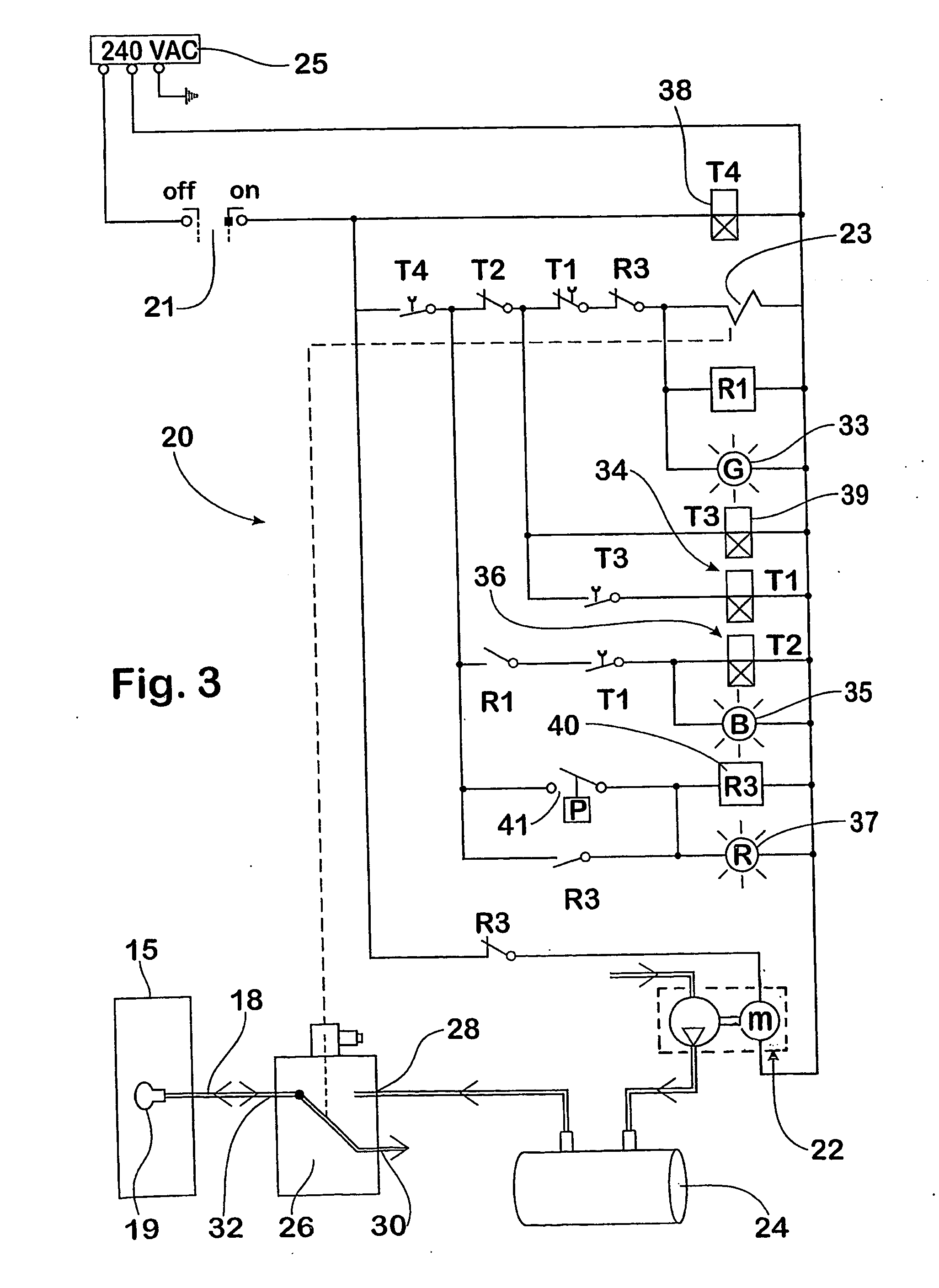
[0054] Typically the apparatus also includes typical safety features such as a pressure cut-out switch to prevent over-pressurising the storage tank.

Problems solved by technology

They typically result from externally applied trauma as a result of accidents, such as falls, motor vehicle accidents, sporting injuries or the like.
However it is not really practical to apply an external fixation device to a fracture site simply to get some speeding up of the healing process.
The treatment is simply too complex and too invasive.

Method used


Image

  • Apparatus and method for treatment of long bone fractures
  • Apparatus and method for treatment of long bone fractures
  • Apparatus and method for treatment of long bone fractures

Examples


Embodiment Construction

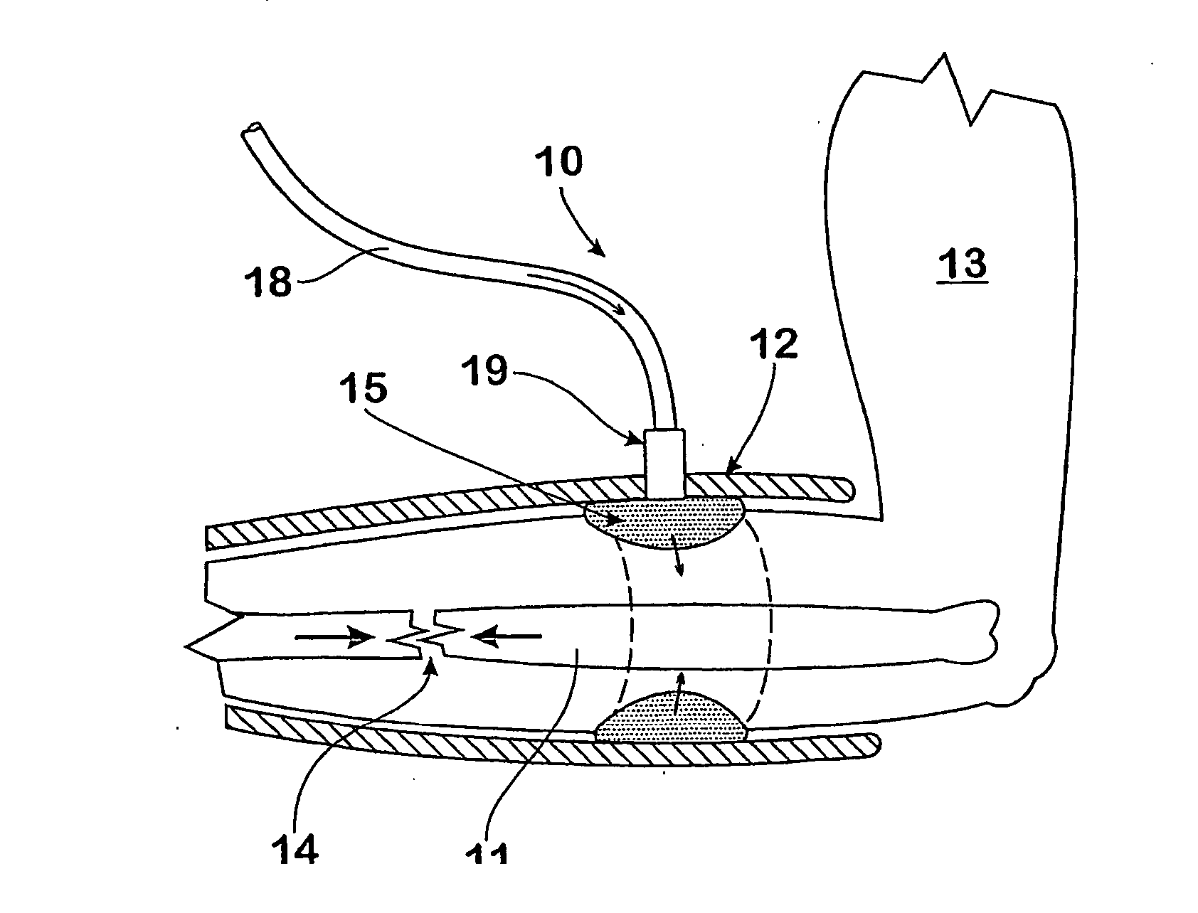
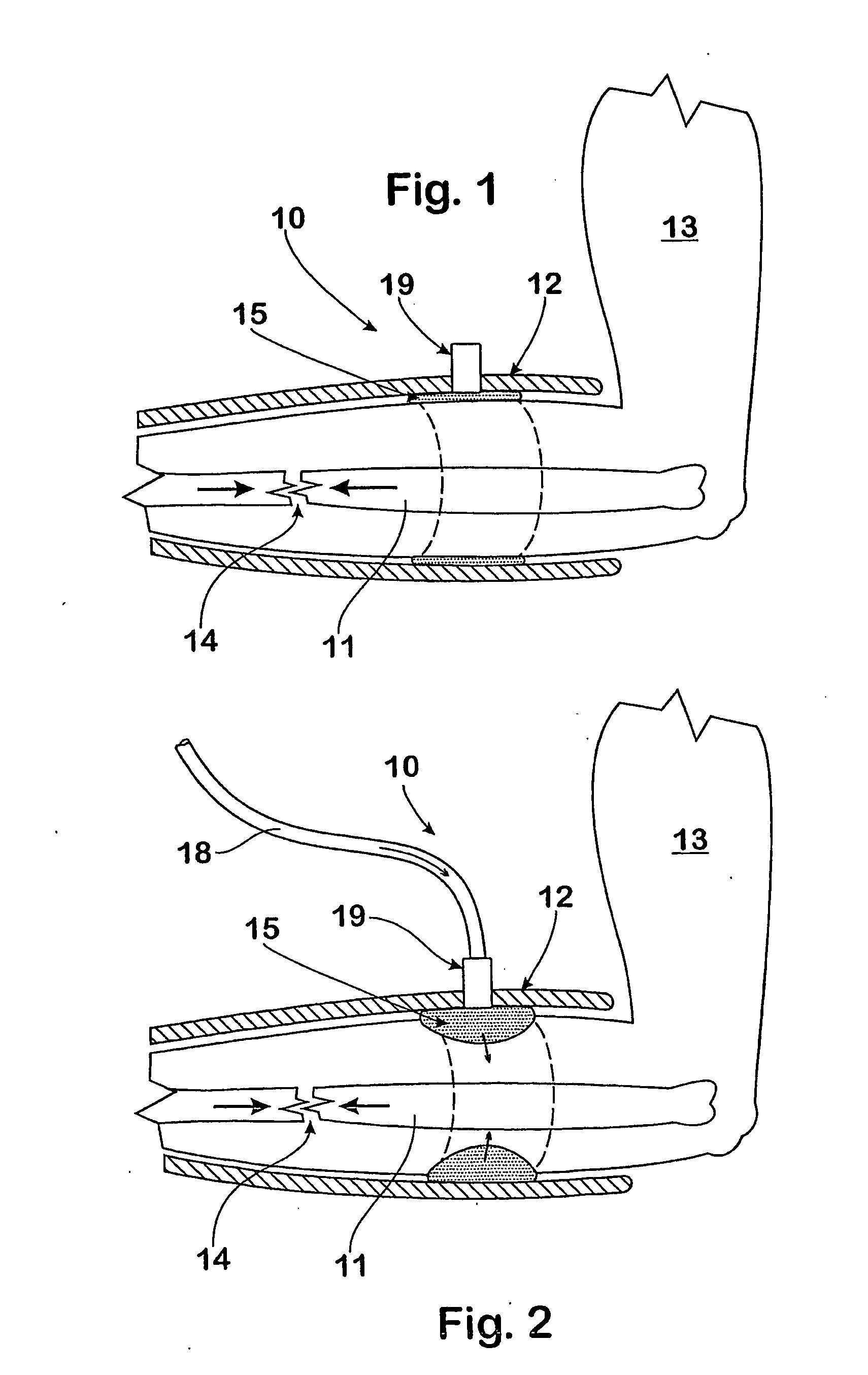
[0067] In FIGS. 1 and 2, reference numeral 10 refers generally to an apparatus in accordance with a first embodiment of the invention. The apparatus 10 includes an immobilisation cast 12 for a fracture 14 of the distal radius 11 of a patient. The cast 12 is fitted around the fractured arm 13 of the patient and a force application member 15 is sandwiched between the immobilisation cast 12 and the outer surface or skin of arm 13.

[0068] The immobilisation cast 12 may be in the form of a moulded plastic cast or else in the form of a well known plaster cast that is shaped to fit the arm of the patient. The structure and function of the immobilisation cast 12 would be well known to persons skilled in the art and will not be described in further detail in this specification.

[0069] The force application member 15 in the illustrated embodiment comprises an inflatable cuff or sleeve or bladder that extends circumferentially around the arm of the patient. The cuff 15 is similar to an inflata...


PUM


Abstract

An apparatus and method for treating a long bone fracture in the limb of an animal wherein a non-invasive technique is provided for intermittently inducing a shortening in length of the skeletal musculature surrounding the long bone, whereby a compressive force may be intermittently applied to the fractured bone. Suitably a radial inward force is applied substantially fully around the circumference to the limb, by an inflatable cuff or sleeve, that is transmitted to the surrounding muscles. Alternatively, electrical signals cause active contraction of the musculature. The treatment may include the application of about 55 to 65 compressions each day for at least 10 days, and commencing within about 7 days of the fracture being sustained. The compressions, applied with frequency in the range of 0.05 Hz to 2 Hz, are desirably just short of that which produces fracture site pain and the intensity of the compressions may be increased between treatment sessions, consistent with heating.

Description

BACKGROUND OF THE INVENTION [0001] 1. Field of the Invention [0002] This invention relates to a method of treating a long bone fracture in a warm-blooded animal, particularly a human being, in order to promote the healing of the fracture. The invention also extends to an apparatus for use in promoting the healing of long bone fractures and a compression device for use with the apparatus. [0003] This invention relates particularly, but not exclusively, to a method and apparatus for treating fractures of the distal radius, i.e. of the forearm. It will therefore be convenient to hereinafter describe the invention with reference to this example application. It is to be clearly understood however that the invention is capable of broader application, for example it might be applied to leg bones and also other long bones. [0004] 2. Discussion of the Background Art [0005] Long bone fractures are fairly common injuries for animals, including human beings. They typically result from externall...

Claims


Application Information

Patent Timeline
IPC IPC(8): A61F5/01A61F5/058A61N1/36
CPCA61F5/012A61N1/36003A61F5/05816
Inventor CHALLIS, MURRAY JOHNHICKEY, TERENCE JOHN
Owner THE UNIV OF QUEENSLAND
Learn More