Method for comparison of a test fingerprint, which is in the form of an image strip sequence, with a stored reference fingerprint, and a suitable apparatus for carrying out the method

Inactive Publication Date: 2005-03-03
INTEL CORP
View PDF11 Cites 14 Cited by
  • Summary
  • Abstract
  • Description
  • Claims
  • Application Information

AI Technical Summary

Benefits of technology

[0008] An object of the invention is to specify a method for comparison of a test fingerprint, which is obtained in the form of an image strip sequence, with a reference fingerprint, and to specify a suitable apparatus in which a low-cost strip sensor may be used, while nevertheless avoiding the computation-intensive reconstruction (which is associated with problems) of an area test fingerprint from the recorded image strips.
[0011] The method according to the invention is a direct single-stage approach, in which the test fingerprint and the reference fingerprint are compared without explicit reconstruction of an area image being required from the image strip sequences of the test fingerprint. This makes use of the discovery that there is a short distance between two fingerprints when there is a short distance between the individual image strips, which reproduce different finger areas, of the test fingerprint and image strips of a reference fingerprint (which is in the form of an image strip sequence) or sections of a reference fingerprint which is in the form of an area image. The identification result is thus composed of a number of result elements. The distance between two image sections or image strips is a measure of the similarity of the image sections or image strips. A short distance in this case corresponds to high similarity. Suitable distance functions may be freely defined. Simple distance functions are, for example, the mean square distance, calculated in pixels, between two image sections, or the correlation between the image sections. The different finger areas may be non-overlapping or partially overlapping. The optimum situation for identification is for the image strips to reproduce precisely mutually adjacent areas of a fingerprint. When using a strip sensor to record an image, for example, this condition is satisfied only when the speed at which the finger is drawn over it is matched exactly to the time interval between the recording of two image strips. In practice, this is not possible. If the finger is moved more slowly than the optimum speed, the recorded image strips overlap. This results in more computation complexity than the optimum. If the finger is moved more quickly, this results in gaps between the image strips, so that fewer image strips are available overall for the comparison. This results in a lower identification confidence level.
[0012] The influence of variations in the recording of the test and reference fingerprints can be reduced if the images are each converted to a normalized representation. This leads to the expectation that the distance function can be calculated more accurately and more reproducibly.
[0014] It is particularly advantageous that there are no redundant computational steps, as need to be carried out in the case of a two-stage method on the one hand for image reconstruction and on the other hand for image comparison. The method is thus particularly efficient.
[0018] In one preferred embodiment, the image strips of the test fingerprint and the reference fingerprint are broken down into image rows, and an individual distance value is then determined for each image row. This further improves the identification confidence level, since distortion resulting from fluctuating speeds at which the finger is drawn over the surface have less influence on the analysis of individual image rows.

Problems solved by technology

In practice, this is not possible.
This results in more computation complexity than the optimum.
If the finger is moved more quickly, this results in gaps between the image strips, so that fewer image strips are available overall for the comparison.
This results in a lower identification confidence level.

Method used


Image

  • Method for comparison of a test fingerprint, which is in the form of an image strip sequence, with a stored reference fingerprint, and a suitable apparatus for carrying out the method
  • Method for comparison of a test fingerprint, which is in the form of an image strip sequence, with a stored reference fingerprint, and a suitable apparatus for carrying out the method
  • Method for comparison of a test fingerprint, which is in the form of an image strip sequence, with a stored reference fingerprint, and a suitable apparatus for carrying out the method

Examples


Embodiment Construction

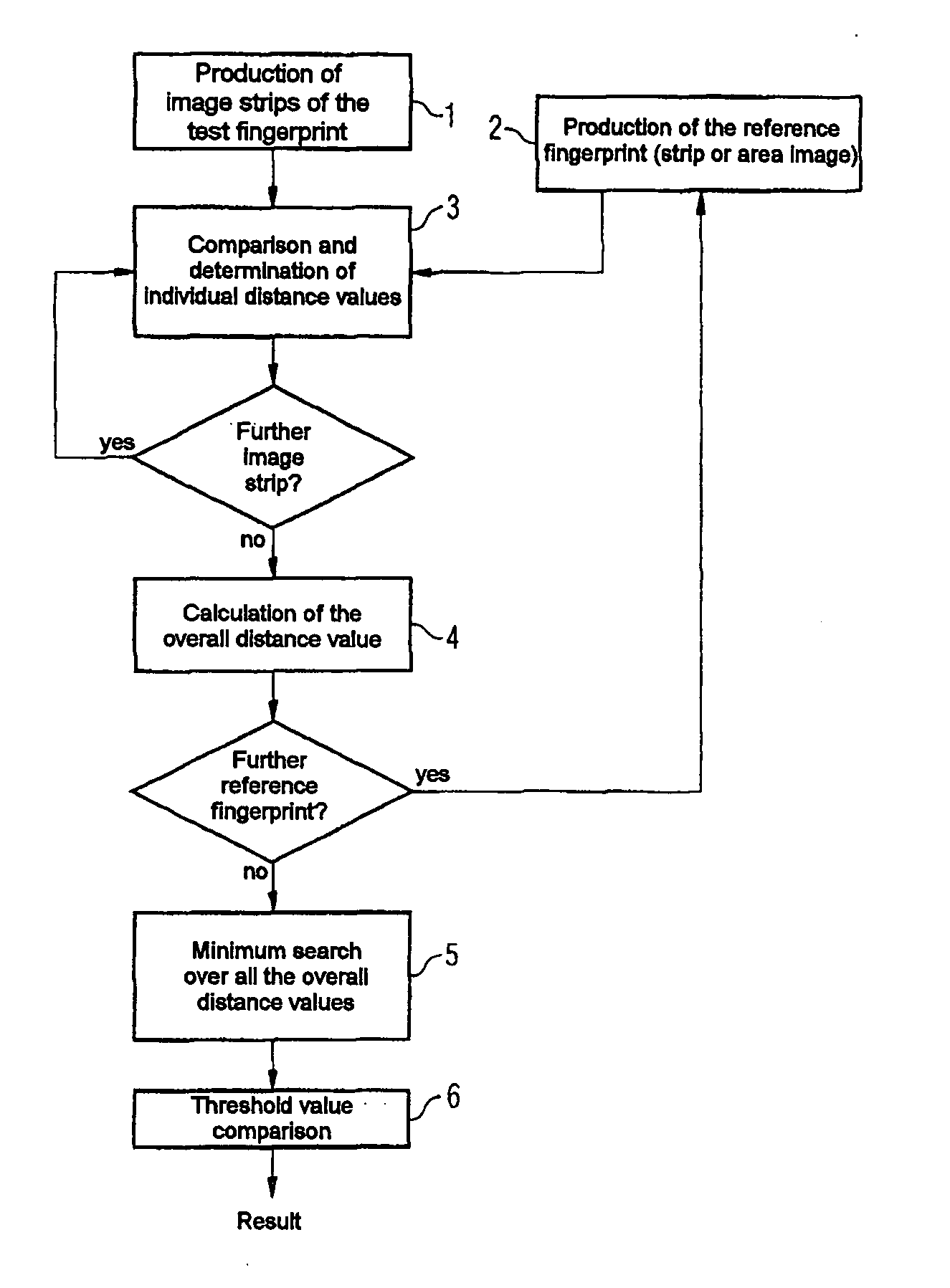
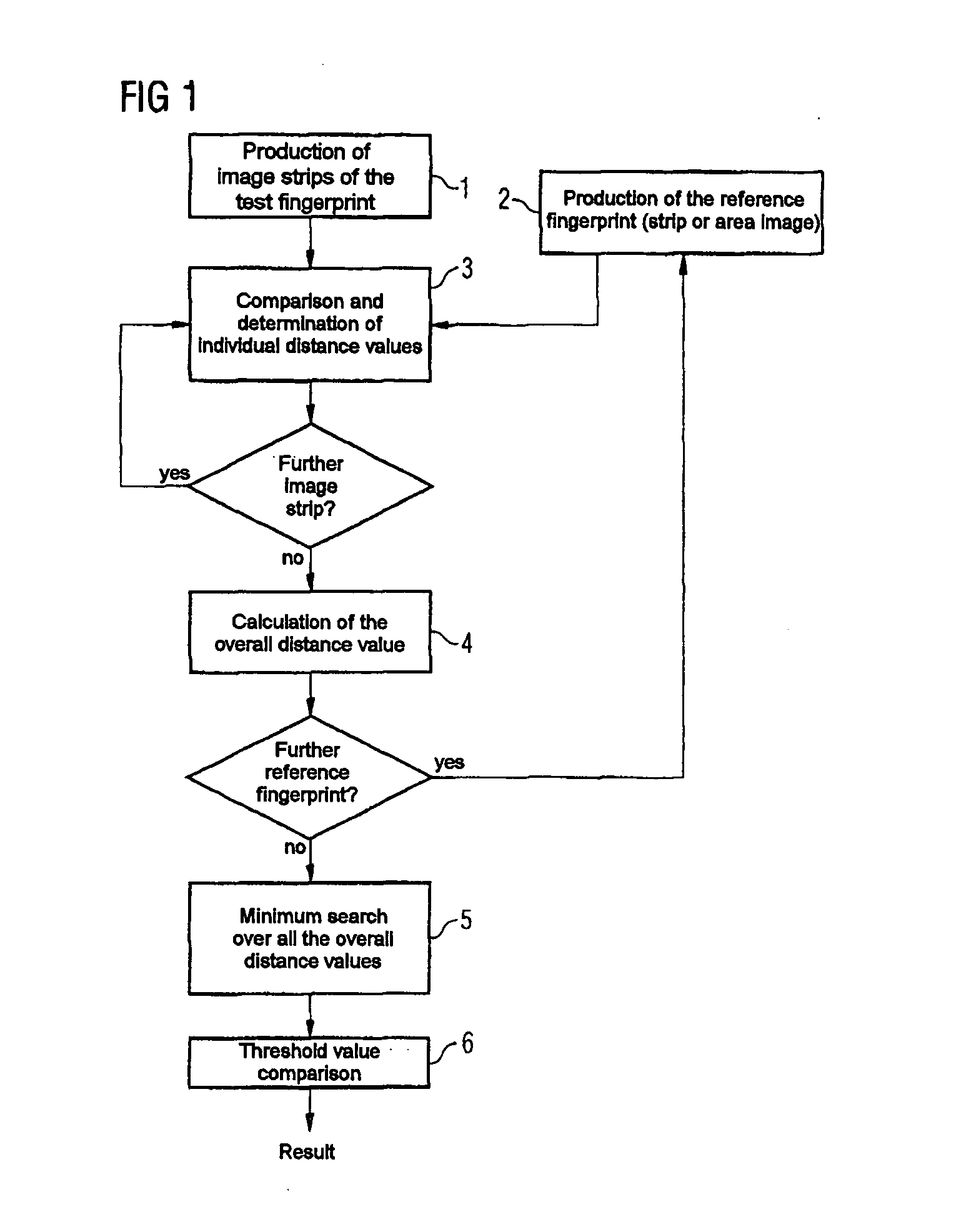
[0027]FIG. 1 shows the procedure for a method according to the invention. Image strips of a test fingerprint are produced in a first step 1, preferably by means of a capacitive strip sensor, which records image sections of the finger in the form of strips while the finger is drawn over it. The invention is, however, not dependent on the sensor principle. Furthermore, a reference fingerprint is produced in a step 2, for example from a memory. The reference fingerprint may be in the form of image strips or an area image, in which case one image strip of the test fingerprint would in the latter case be compared with sections of the reference fingerprint, in order to carry out a comparison process.

[0028] Whether the reference fingerprint is stored in the form of a strip sequence or as an area image depends, for example, on the method for production of the fingerprint. If the reference fingerprint is likewise obtained by means of a strip sensor, which may also be identical to the strip ...


PUM


Abstract

Method of comparing a test fingerprint with a stored reference fingerprint. The stored reference fingerprint and an image strip sequence of the test fingerprint are produced, wherein image strips of the image strip sequence represent different areas of the test fingerprint. Individual distance values between each image strip of the test fingerprint and at least one section of the reference fingerprint using a distance function are determined. An overall distance value from the individual distance values are determined, the overall distance value being a measure of similarity between the test fingerprint and the reference fingerprint.

Description

CROSS-REFERENCE TO RELATED APPLICATION [0001] This application is based on German Patent Application Serial No. 10339743.4, which was filed Aug. 28, 2003, and which is incorporated herein by reference in its entirety. FIELD OF THE INVENTION [0002] The invention relates to a method for comparison of a test fingerprint with a stored reference fingerprint, with the test fingerprint being produced in the form of a sequence of image strips. The reference fingerprint may be in the form of an area image, or likewise in the form of an image strip sequence. The invention furthermore relates to an apparatus for identification of fingerprints by means of a fingerprint sensor, which is in the form of a strip, for recording image strips of a test finger, and having a memory for storage of reference fingerprints as an area image or image strip sequence. BACKGROUND OF THE INVENTION [0003] In the case of fingerprint sensors, it is known for a sensorally sensitive surface to be provided, which is ap...

Claims


Application Information

Patent Timeline
IPC IPC(8): G06K9/00
CPCG06K9/00087G06V40/1365
Inventor MORGUET, PETER
Owner INTEL CORP
Why Eureka
Try Eureka