Developing device and process cartridge

a technology of developing device and process cartridge, which is applied in the direction of electrographic process apparatus, instruments, optics, etc., can solve the problems of affecting the development device, the influence of the sealing member passing through the end portion seal member to be leaked to the outside of the developing device, and the influence of the increase in cost and mass-productivity, so as to reduce the influence of toner leakage and increase the cost

Inactive Publication Date: 2013-11-12
CANON KK
View PDF32 Cites 36 Cited by
  • Summary
  • Abstract
  • Description
  • Claims
  • Application Information

AI Technical Summary

Benefits of technology

[0010]A principal object of the present invention is to provide a developing device and a process cartridge which less influence on toner leakage and an increase in cost and have realized downsizing.
[0014]a first seal member, provided at the opening along an end portion of the developing roller, for preventing toner leakage from a gap between the opening and the developing roller; and
[0022]a first seal member, provided at the opening along an end portion of the developing roller, for preventing toner leakage from a gap between the opening and the developing roller; and

Problems solved by technology

If the end portion seal member and the end portion of the developer supplying roller which was a rotatable member were contacted to each other, the toner was liable to enter the gap of the end portion seal member, so that there was a possibility that the toner passed through the gap of the end portion seal member to be leaked to the outside of the developing device.
Further, when the tolerance of the parts is strictly set in order to prevent the contact between the end portion seal member and the developer supplying roller, there is a possibility of influences on an increase in cost and on mass-productivity.
Further, also in the case where a constitution in which piles of the end portion seal member are not removed even when the end portion seal member and the end portion of the developer supplying roller which is the rotatable member are contacted to each other is employed, similarly as in the above case, there is the possibility of influences on the increase in cost and on the mass-productivity.

Method used


Image

  • Developing device and process cartridge
  • Developing device and process cartridge
  • Developing device and process cartridge

Examples


embodiment 1

(Embodiment 1)

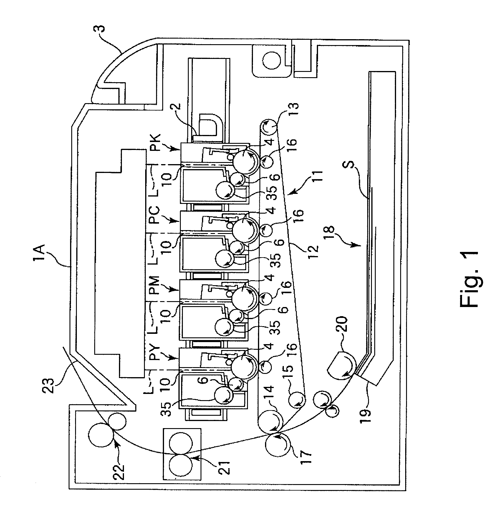
[0037]FIG. 1 show a schematic sectional structure of a color electrophotographic image forming apparatus in this embodiment in which the developing device and the process cartridge according to the present invention are mounted. This image forming apparatus 1A (hereinafter referred to as an apparatus main assembly 1A) is a four color-based full-color laser printer using the electrophotographic process and effects image formation on a recording material S. This apparatus is of a process cartridge type in which the process cartridge is detachably mountable to the apparatus main assembly 1A and a color image is formed on the recording material S.

[0038]Here, in the following description, with respect to the apparatus main assembly 1A, the side (surface) on which an apparatus opening and closing door 3 is provided is referred to as a front side (surface), and a side (surface) opposite to the front side (surface) is referred to as a rear side (surface). The left and right of...

embodiment 2

(Embodiment 2)

[0074]FIG. 7 shows the developing device of the present invention in this embodiment. In this embodiment, the general structure of the developing device is the same as that in Embodiment 1, thus being omitted from description. The developing device in this embodiment is different in end portion constitution from the developing device in Embodiment 1.

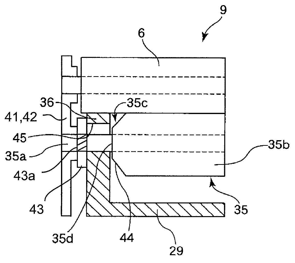
[0075]That is, in this embodiment, the outer diameter of the small diameter portion 44 at the end portion 35c of the cylindrical elastic member 35b is smaller toward the extreme end of the cylindrical elastic member 35b, i.e., the end portion 35d. The outer diameter portion of the end surface 35d of the cylindrical elastic member 35b is located below the bearing surface 45 for application of the end portion seal member 36 in the developing container 29. That is, the outer diameter of the end surface 35d is made smaller than the outer diameter of the central portion so that the end surface 35d and the end portion seal Member...

embodiment 3

(Embodiment 3)

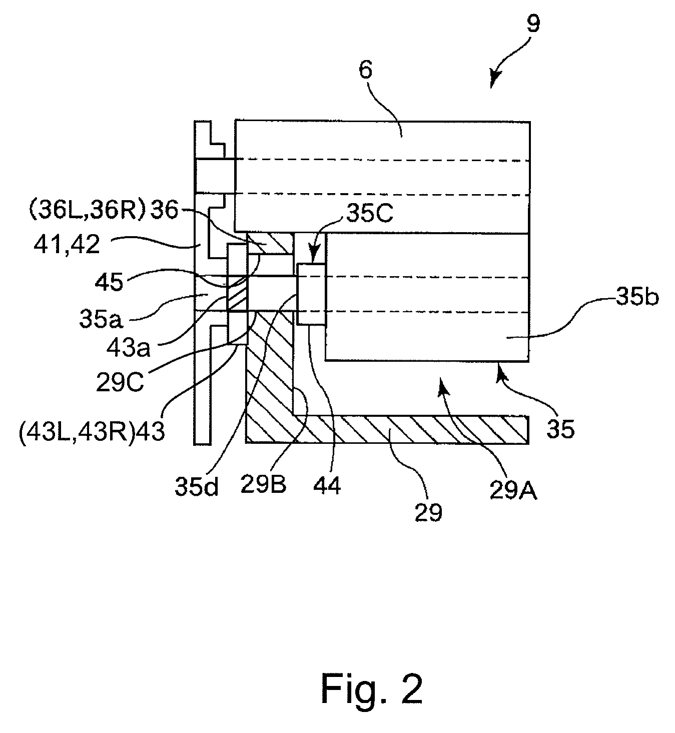
[0082]FIG. 11 shows the developing device of the present invention in this embodiment. In this embodiment, the general structure of the developing device is the same as that in Embodiment 1, thus being omitted from description. The developing device in this embodiment is different in end portion constitution from the developing device in Embodiment 1.

[0083]That is, in this embodiment, the end portion 35c (end surface 35d) of the cylindrical elastic member 35b is contacted to the opening 29A-side end portion (inner end surface 29B) of the developing container 29.

[0084]In the conventional developing device, when the end portion 35c of the cylindrical elastic member 35b, i.e., the end surface 35d was contacted to the opening 29A-side end portion (inner end portion 29B) of the developing container 29, the end surface 35d of the cylindrical elastic member 35b and the end portion seal member 36 were contacted to each other, so that there was a possibility of the occurrence o...


PUM


Abstract

A developing device includes a developing container, provided with an opening, for containing a developer; a developing roller, provided at the opening, for forming a developer image on an image bearing member; a seal member, provided at the opening along an end portion of the developing roller, for preventing toner leakage from a gap between the opening and the developing roller; and a developer supplying roller, including a core material and a cylindrical elastic member which is provided around the core material and is contacted to the developing roller, for supplying the developer to the developing roller. The cylindrical elastic member has an end surface and a central portion with respect to a longitudinal direction thereof. The end surface has an outer diameter larger than that of the central portion so as to be in non-contact with the seal member.

Description

FIELD OF THE INVENTION AND RELATED ART[0001]The present invention relates to a developing device and a process cartridge which are to be used in an electrophotographic image forming apparatus, of an electrophotographic type, such as a copying machine or a printer.[0002]Here, the electrophotographic image forming apparatus forms an image on a recording material by using the electrophotographic method. Examples of the electrophotographic image forming apparatus may include an electrophotographic copying machine, an electrophotographic printer (e.g., a laser beam printer, an LED printer or the like), a facsimile machine, a word processor, and the like.[0003]Further, the process cartridge is prepared by integrally assembling an electrophotographic photosensitive member and, as process means, a charging means, a developing means and a cleaning means into a cartridge, which is detachably mountable to an electrophotographic image forming apparatus main assembly.[0004]Further, the developin...

Claims


Application Information

Patent Timeline
Patent Type & Authority Patents(United States)
IPC IPC(8): G03G15/08
CPCG03G15/0808G03G15/0898
Inventor KUBO, YUKIONITTANI, SUSUMUKASHIIDE, YOSUKE
Owner CANON KK
Why Eureka
Try Eureka