
Method and device for determining the pressure in brake systems

a technology of brake system and pressure sensor, which is applied in the direction of fluid tightness measurement, force/torque/work measurement apparatus, instruments, etc., can solve the problems that the known methods and devices named in the related art cannot provide optimal results in every situation, and the use of pressure sensors cannot be eliminated. , to achieve the effect of increasing the driving stability and/or safety of vehicles, eliminating the use of pressure sensors, and increasing quality and safety

Inactive Publication Date: 2002-09-10
ROBERT BOSCH GMBH
View PDF18 Cites 37 Cited by
  • Summary
  • Abstract
  • Description
  • Claims
  • Application Information

AI Technical Summary

Benefits of technology

The foregoing gives rise to the object to determine a pressure quantity in a braking system, an admission pressure and / or a wheel brake pressure, in particular, as an absolute value without the use of pressure sensors. In doing so, it is possible to use quantities which are already available in the particular control systems such as an antilock braking system (ABS), traction control system (TCR) an electronic stability program (ESP), a brake booster (HBV, HBU), a cruise control system (ACC), hill holder control (HHC) or hill descent control (HDC) without having to explicitly detect pressure quantities. Accordingly, the methods and the particular corresponding device for increasing the driving stability and / or safety in vehicles can be used for all systems or controls that influence the braking effect.
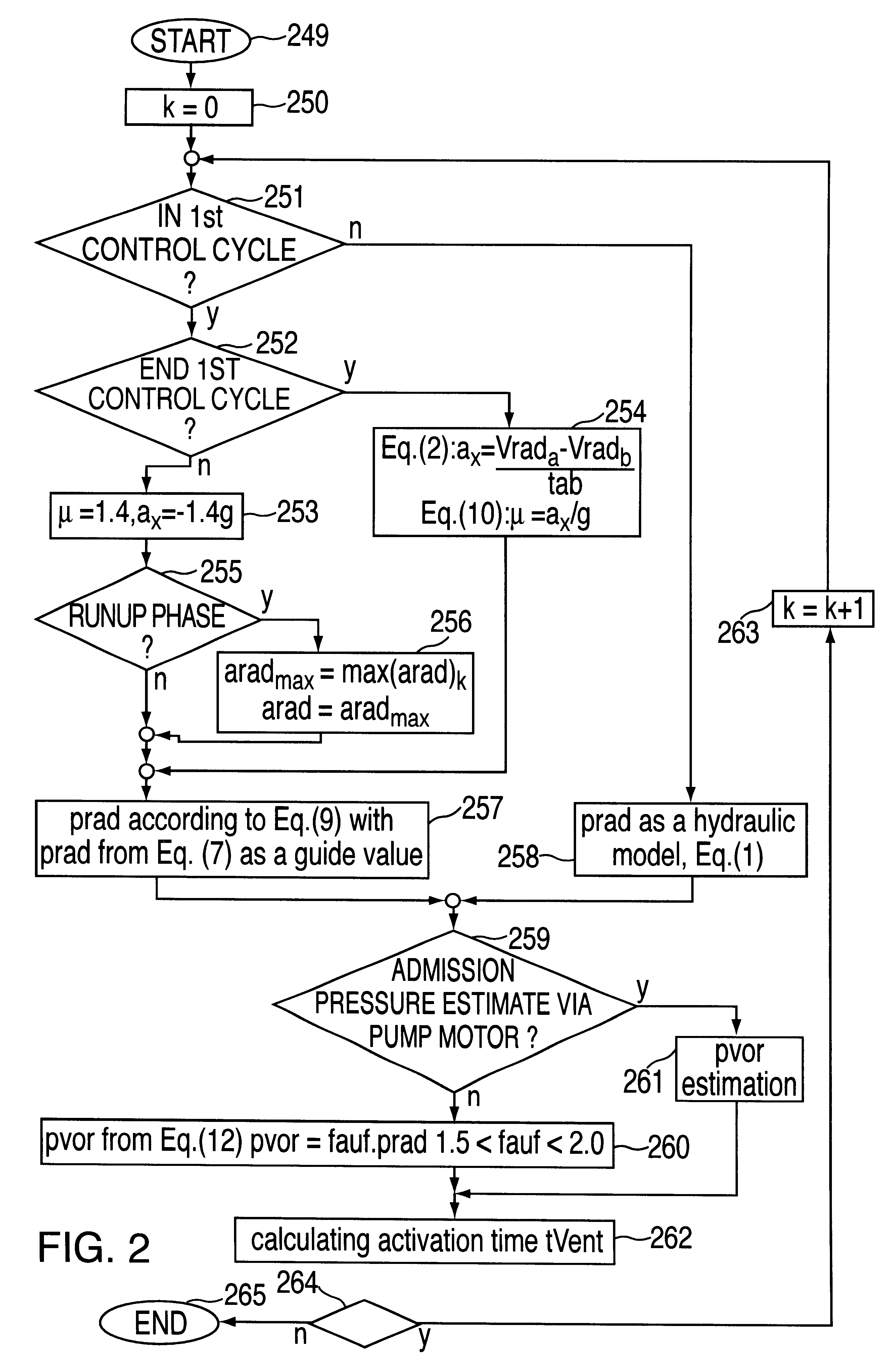
Using the methods according to the present invention in the device according to the invention, in particular, makes it possible to eliminate the use of pressure sensors. In particular, it is possible to eliminate the admission pressure sensor system used in the above-cited known methods. The values required, such as the starting value and the admission pressure value in estimating the wheel braking pressure or wheel pressure, can be determined using available signals such as wheel velocity, rotational speed or voltage or power consumption of the pump motor.
The idea of pressure estimation, the determination of the admission pressure, in particular, lies in the fact that the required torque of the pump motor in return delivery is directly proportional to the admission pressure. The disadvantage of pressure detection as a function of rotational speed is compensated by the use of power consumption as a measured value. This is possible since the power consumption of the pump motor is a function of the associated torque. Accordingly, the power consumption of the pump motor increases in linear proportion to the torque. That which, for example, the electromagnetically induced overtravel voltage, the current signal is continuously available for analysis and not only when the pump is in operation.
The voltage and / or temperature dependence of a value used as a measure of rotational speed can be eliminated or compensated by the use of currents, of at least one motor current, in particular. Also, the influence of manufacturing variance is then of less significance than in the rotational speed-forming value such as the electromagnetically induced motor voltage or overtravel voltage.
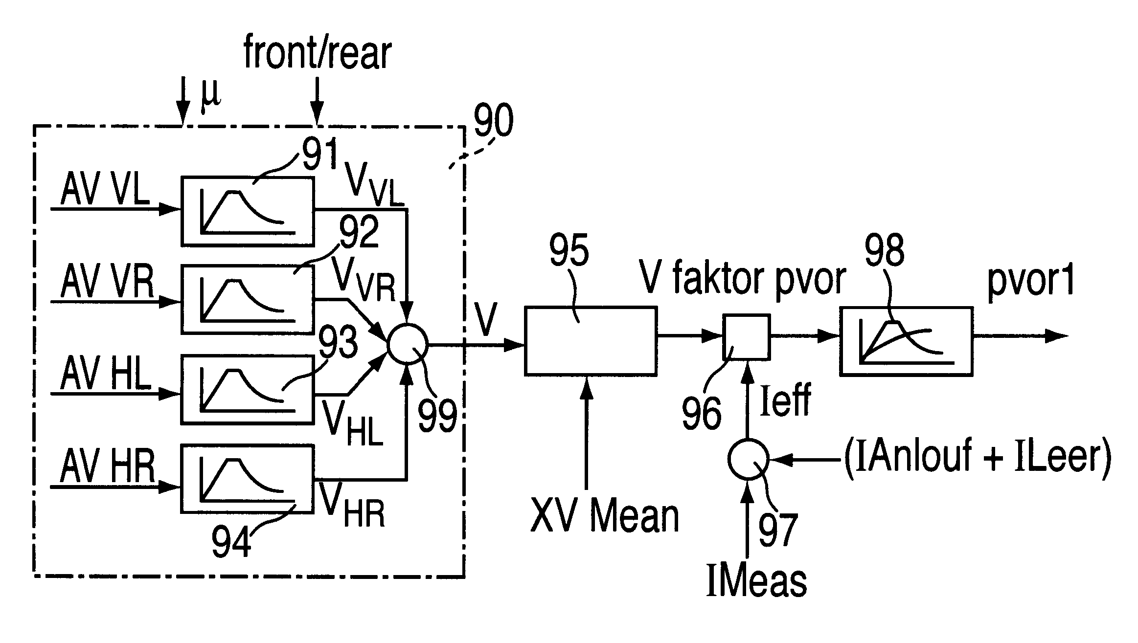
It is additionally advantageous to include a pressure-dependent factor in a relation between pressure reduction time and the volume of the pressure medium in question, in a pressure accumulator, in particular, for the pressure estimation since this takes into account the dependence of this relation or of this interrelationship on the pressure level and accordingly on the further increase of the quality and safety of the methods and device.
A possible temperature dependence of the estimation, of the interrelationship between pressure reduction time and the volume cited in a preceding paragraph, in particular, is taken into account by applying a similarity or comparability of the temperature dependence of a current and a viscosity of the pressure medium and then including them in the method and device according to the invention. Moreover, an assumed and specified dependence of a current on the viscosity of the pressure medium advantageously even allows a temperature and estimation error to be compensated by one-time, constant, or continuous, variable inclusion of this current in the methods and particular device, for example, by forming a minimum in the current curve.

Problems solved by technology

In addition, with this method, pressure sensors can only be eliminated in the determination of a differential pressure between a first line and a second line.
Thus it is evident that the known methods and devices named in the related art cannot provide optimum results in every respect.

Method used


Image

  • Method and device for determining the pressure in brake systems
  • Method and device for determining the pressure in brake systems
  • Method and device for determining the pressure in brake systems

Examples


Embodiment Construction

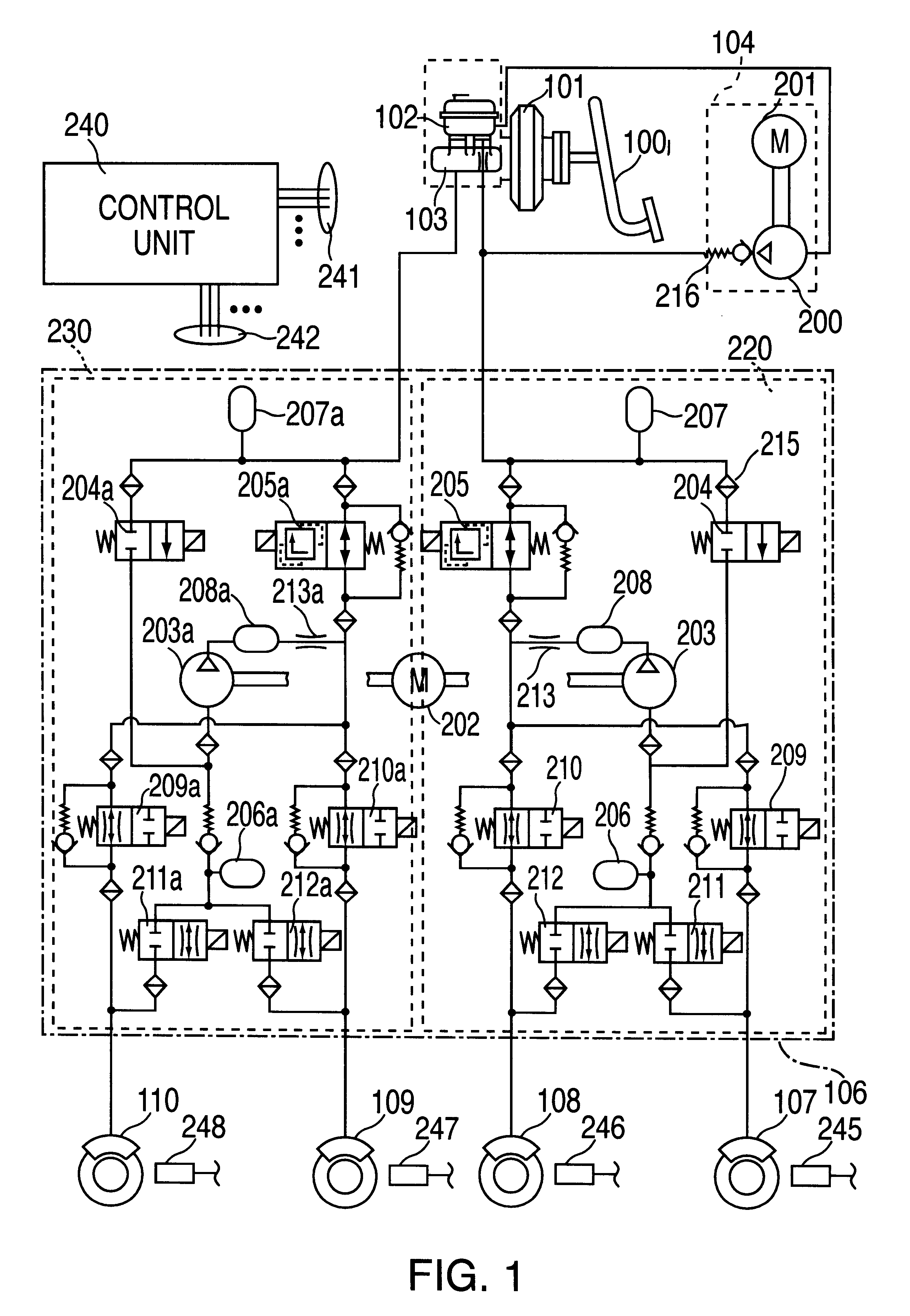
The exemplary embodiments are described with reference to the hydraulic vehicle braking system shown in FIG. 1 having a control unit 240 and wheel speed sensors 245 to 248. This braking system is selected here as an example. The invention, however, can be used in a large number of systems influencing the braking effect and corresponding braking systems. The functionalities in relation to the systems influencing braking effect, ABS, TCS, FDR, in particular, can either be integrated in control unit 240 or embedded in an additional control unit or higher-level logic, the latter then being in communication with control unit 240.

Brake pedal 100 is connected to brake master cylinder 103 by a piston rod, for example, via a brake booster 101. A brake fluid reservoir 102 is connected to brake master cylinder 103 which has a dual circuit in this case. A charging pump 104 is connected between them via a line for the pressure medium. The charging line of charging pump 104 opens into a master br...


PUM

PropertyMeasurementUnit
temperatureaaaaaaaaaa
pressureaaaaaaaaaa
pressureaaaaaaaaaa

Abstract

Device and method for determining a wheel braking pressure and / or an admission pressure in a braking system in which pressure medium is introduced from a reservoir for the pressure medium having an admission pressure into a wheel brake through at least one shutoff device for inlet and / or outlet and / or passage of a pressure medium, it being possible to remove pressure medium from the wheel brake through at least one means delivering the pressure medium. In so doing, a pressure quantity representing the admission pressure is estimated, at least one operating state of at least one actuator in the braking system is detected and the wheel braking pressure is estimated as a function of the estimated admission pressure and the detected operating states.

Description

BACKGROUND INFORMATIONThe invention relates to a method and a device for determining pressure quantities, in particular, those of a wheel braking pressure and / or an admission pressure in a braking system of a vehicle having an antilock braking system (ABS) and / or traction control system (TCR) and / or electronic stability program (ESP), in accordance with the precharacterizing portions of the independent claims.A braking pressure control system is known from German Patent Application 40 30 724 A1 in which desired braking pressures are determined for the wheel brake cylinders based on measured values and estimated values. Activation times for a hydraulic system having inlet valves are determined from the desired braking pressures using a hydraulic model. The actual braking pressure in the wheel brake cylinder is estimated from the brake circuit pressure, which is assumed to correspond to the admission pressure of the braking system measured by a sensor, and the activation times of the ...

Claims


Application Information

Patent Timeline
Patent Type & Authority Patents(United States)
IPC IPC(8): B60T8/40B60T8/48B60T8/34
CPCB60T8/40B60T8/4059B60T8/4881
Inventor LOHNER, HERBERTDOMINKE, PETERCAO, CHI-THUANWEISS, KARL-JOSEFWISS, HELMUTZIERHUT, ANDREASFIEDLER, JENS
Owner ROBERT BOSCH GMBH
Learn More