Suspension System

a suspension system and suspension technology, applied in the direction of pedestrian/occupant safety arrangement, transportation items, tractors, etc., can solve the problems of vehicle overturning, vehicle overturning, frame tilting, etc., to reduce the impact on the overall structure of the vehicle, and increase the life of load-bearing parts

Inactive Publication Date: 2008-05-01
DEERE & CO
View PDF14 Cites 27 Cited by
  • Summary
  • Abstract
  • Description
  • Claims
  • Application Information

AI Technical Summary

Benefits of technology

[0023]The suspension system according to the invention constitutes a suspension with hydraulic roll stabilization for the sprung axle of the vehicle. It is advantageous here that the sprung axle can be sprung without the need for additional mechanical measures for roll stabilization. The aforementioned suspension system has two hydraulic cylinders, which can be operated independently of one another and which resiliently support the frame of the vehicle in relation to the axles of the vehicle. In order to prevent rolling movements occurring whilst underway, the suspension system is provided with electrically and proportionally adjustable orifices, in each case arranged between hydraulic cylinder and hydraulic accumulator. The orifices ensure that the damping rate of the respective hydraulic cylinder is adjustable according to the movements of the frame relative to the axle. By varying the damping rate and an associated stiffening of the system, it is possible to hydraulically suppress rolling movements. For detection of the rolling movement, corresponding sensors or other means are provided, which serve to measure and evaluate the position and above all the variation in the position of the frame relative to the vehicle axles. A sprung axle considerably reduces the impacts on the overall structure of the vehicle and thus increases the life of load-bearing parts. Owing to the reduced vibrations, even smaller components are less stressed, so that their reliability is increased. The suspension system furthermore brings considerable improvements in ride comfort and increases the driving stability at high speeds. This may also afford time advantages in the operation of the vehicle. A further advantage is that the suspension system according to the invention manages with two hydraulic accumulators, provided that it is ensured that suspension movements cannot lead to a vacuum in the hydraulic accumulators, which except in piston accumulators would lead to damaging of the hydraulic accumulator.

Problems solved by technology

Whereas with the suspension deactivated the vehicle is stable, on activation of the suspension the support width of the vehicle is reduced, with the result that forces may be introduced, which can cause the vehicle to overturn.
Such a tipping movement would occur very rapidly on sudden activation of the suspension and in an extreme case would lead to overturning of the entire vehicle.
Detecting this pressure change is not without problems, since a constrained pressure may be present in the hydraulic cylinder, which has resulted due to external heating or an adjustment of the hydraulic cylinder, for example.
In this case a negative force means that the frame does not rest on the cylinder rod, but instead is pulling on it, which when the rod-side switch valve opens could lead to an extending of the piston rod of the hydraulic cylinder and hence to a tilting of the frame.

Method used


Image

  • Suspension System
  • Suspension System
  • Suspension System

Examples


Embodiment Construction

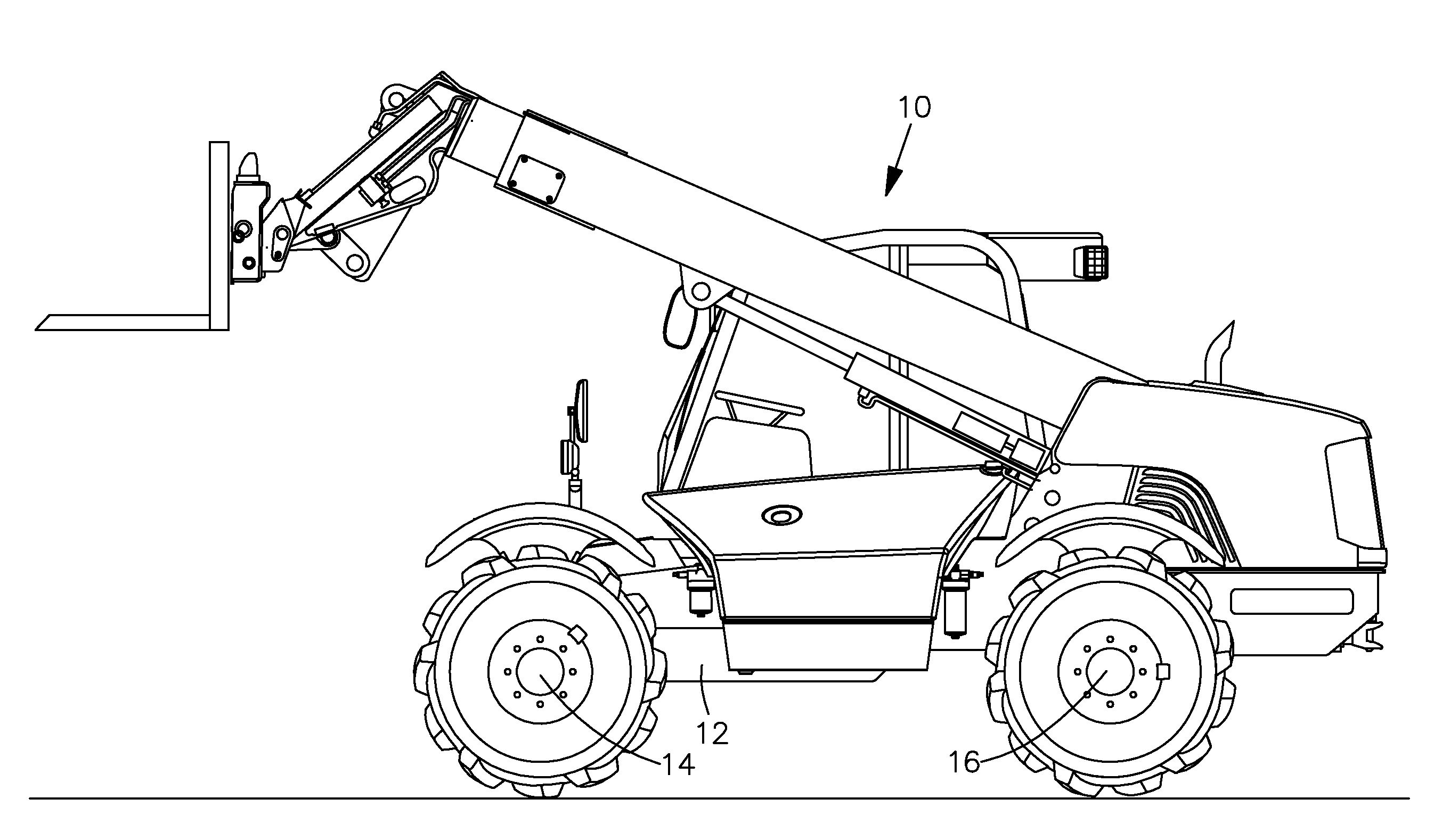
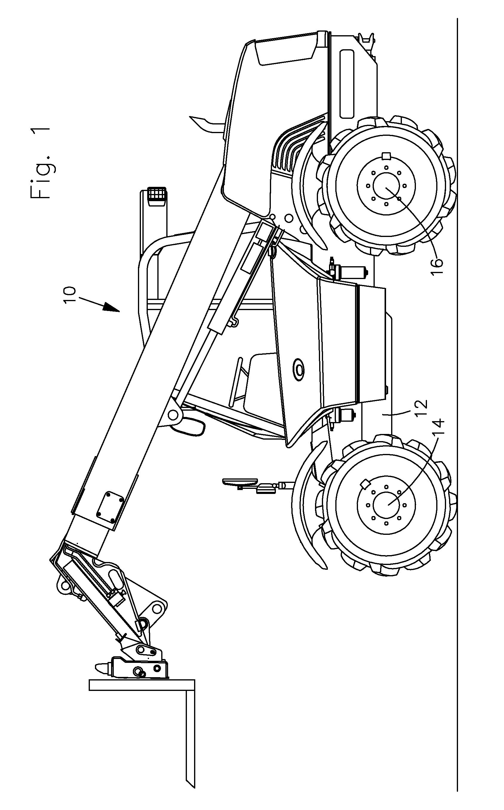
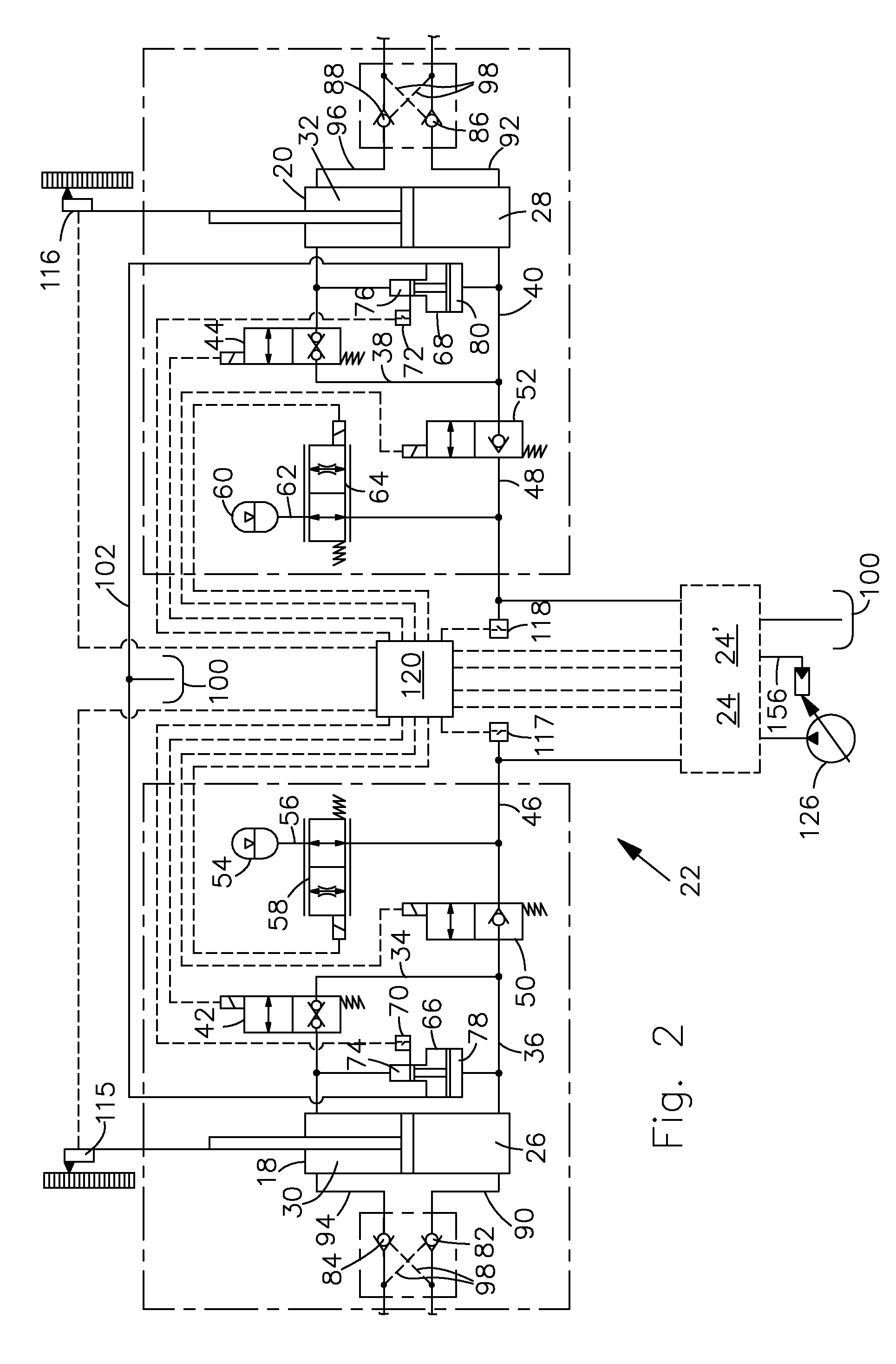
[0031]FIG. 1 shows an agricultural vehicle 10 in the form of a telescopic loader, which has a frame 12, a front axle 14 and a rear axle 16. The rear axle 16 is floating, as is usual for telescopic loaders. The front axle 14 is sprung in such a way that hydraulic cylinders 18, 20, which are part of a suspension system 22 with hydraulic roll stabilization, explained in more detail in FIGS. 2 to 6, extend between the frame 12 and the front axle 14, on either side of the vehicle central longitudinal axis. Similarly, the front axle 12 could also be floating and the hydraulic cylinders for suspension of the rear axle 16 could be correspondingly arranged between the rear axle 16 and the frame 12. It is also feasible to use such a suspension system 22 on a tractor (with or without front loader), a wheeled loader or another loader vehicle.

[0032]The suspension system 22 will be described in detail with reference to FIGS. 2 to 6, the system components for the load state sensing being represent...


PUM


Abstract

A suspension system for an agricultural or construction industry vehicle is described. The suspension system comprises two hydraulic cylinders, which support a frame in relation to an axle of the vehicle, the hydraulic cylinders each having a piston-side chamber and a piston rod-side chamber and each of the chambers of the hydraulic cylinders being connectable to one another via connecting lines provided with a switch valve, a first supply line, which can be connected via a switch valve to the piston-side connecting line of the first hydraulic cylinder, a second supply line, which can be connected via a switch valve to the piston-side connecting line of the second hydraulic cylinder, a hydraulic accumulator, in each case connectable to the supply lines via proportionally adjustable orifices, a hydraulic source, a hydraulic tank, a control valve device, and an electronic control unit. In order to prevent the activation of a suspension state in critical vehicle states, means for the detection and compensation of load states of the vehicle are provided in the suspension system.

Description

FIELD OF THE INVENTION[0001]The invention relates to a suspension system for an agricultural or construction industry vehicle, in particular a loader vehicle, having a first and a second hydraulic cylinder, which support a frame of the vehicle in relation to an axle of the vehicle, the hydraulic cylinders each having a piston-side chamber and a piston rod-side chamber and each of the chambers of the hydraulic cylinders being hydraulically connectable to one another via a piston rod-side connecting line and a piston-side connecting line, the piston rod-side connecting lines each opening into the piston-side connecting lines and being provided with a switch valve, a first supply line, which can be connected via a switch valve to the piston-side connecting line of the first hydraulic cylinder, a second supply line, which can be connected via a switch valve to the piston-side connecting line of the second hydraulic cylinder, a first and a second hydraulic accumulator which can be connec...

Claims


Application Information

Patent Timeline
Patent Type & Authority Applications(United States)
IPC IPC(8): B60G17/04
CPCB60G17/005B66F9/22B60G2200/322B60G2204/46B60G2204/4605B60G2300/022B60G2300/082B60G2400/0511B60G2400/50B60G2400/51B60G2400/5122B60G2400/60B60G2800/0122B60G2800/0194B60G17/0162
Inventor BITTER, MARCUS
Owner DEERE & CO
Why Eureka
Try Eureka