Anode and battery

Active Publication Date: 2005-09-01
MURATA MFG CO LTD
View PDF6 Cites 39 Cited by
  • Summary
  • Abstract
  • Description
  • Claims
  • Application Information

AI Technical Summary

Benefits of technology

[0009] In view of the foregoing, it is an object of the invention to provide an anode capable of preventi

Problems solved by technology

However, the battery capacity of a currently typical lithium secondary battery which uses lithium cobalt oxide as a cathode and graphite as an anode has reached a point of saturation, so it is extremely difficult to substantially increase the capacity of the lithium secondary battery.
However, when charge and discharge are repeated, the anode with a high capacity is broken into small pieces due to severe expansion and shrinkage of an active material, thereby a current collecting property declines, or the decomposition of an electrolyte solution is accelerated due to an increase in a surface area, thereby cycle characteristics are extremely poor.
However, even in the anode, the cycle characteristics

Method used


Image

  • Anode and battery
  • Anode and battery
  • Anode and battery

Examples


examples

[0073] Examples of the invention will be described in detail below referring to FIGS. 1 through 4. In the following examples, like components are donated by like numerals as of the above embodiment.

examples 1-1 through 1-5

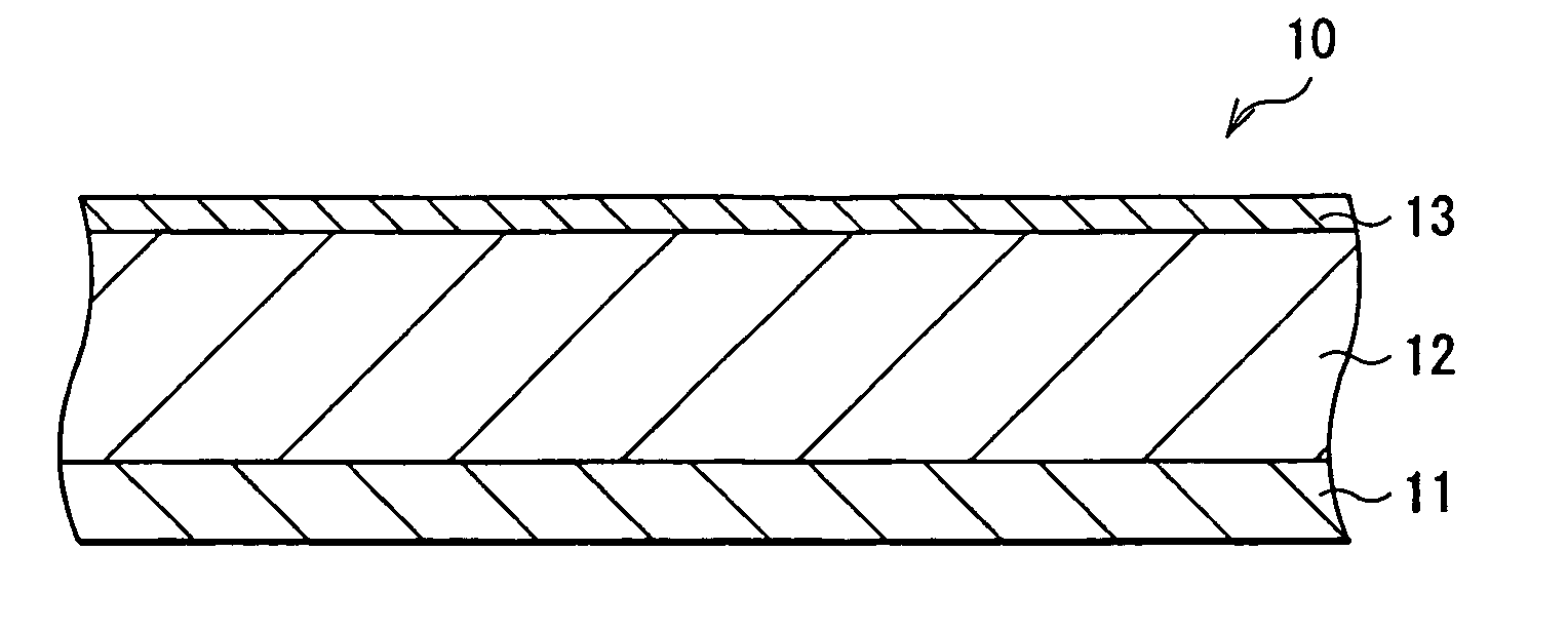
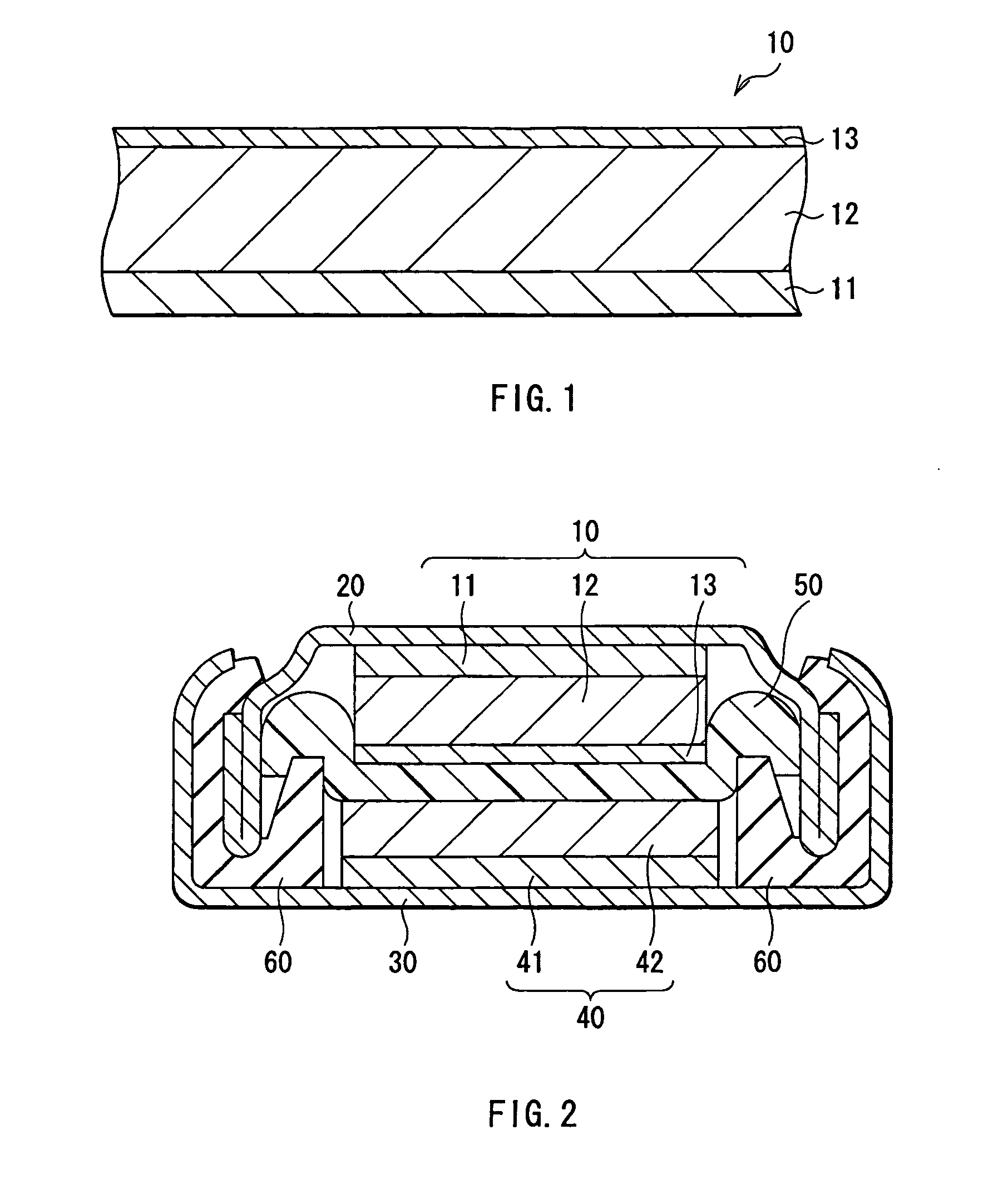
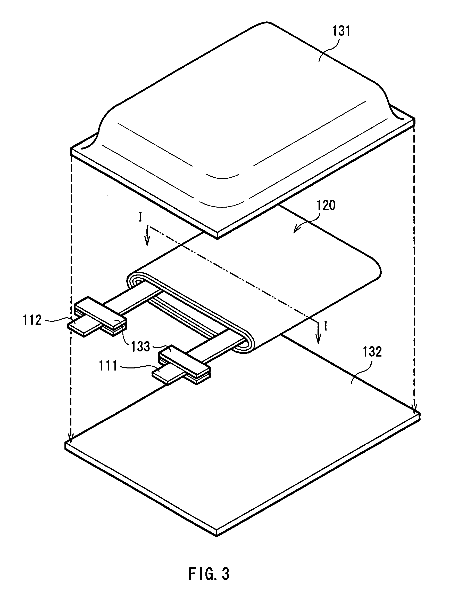
[0074] Secondary batteries shown in FIGS. 3 and 4 were formed. At first, the anode active material layer 12 made of silicon was formed on the anode current collector 11 made of copper foil with a thickness of 15 μm by a sputtering method. Next, lithium metal was deposited on the anode active material layer 12 by a vacuum deposition method. An atmosphere at the time of depositing lithium metal was less than 1×10⁻³ Pa, and the deposition speed was 5 nm / s to 10 nm / s. The amount of deposited lithium metal, that is, the amount of lithium inserted into the anode active material layer 12 in advance was 5% of the anode capacity.

[0075] After lithium metal was deposited, an inactivated gas which included a mixture of carbon dioxide and argon at a volume ratio of 20:80 was introduced into a vacuum chamber at a flow rate of 50 cm3 / min (1 atm, 25° C.), and then a process of inactivating the anode active material layer 12 was carried out. After that, an argon gas was introduced into the vacuum c...

examples 9-1 through 9-5 , 10-1 through 10-5 , 1-1 through 11-5 , 12-1 through 12-5

Examples 9-1 through 9-5, 10-1 through 10-5, 1-1 through 11-5, 12-1 through 12-5

[0094] Secondary batteries were formed as in the case of Examples 1-1 through 1-5, 2-1 through 2-5, 3-1 through 3-5 and 4-1 through 4-5, except that the anode active material layer 12 made of tin with a thickness of 5 μm was formed on the anode current collector 11 made of copper foil with a thickness of 15 μm by a vacuum deposition method, and then a heat treatment was performed in an inert atmosphere at 200° C. for 12 hours. As Comparative Examples 9-1 through 9-5, 10-1 through 10-5, 11-1 through 11-5 and 12-1 through 12-5 relative to the examples, secondary batteries were formed as in the case of Examples 9-1 through 9-5, 10-1 through 10-5, 11-1 through 11-5 and 12-1 through 12-5, except that no inactivation process by an inactivated gas was carried out. A charge-discharge test was carried out on the secondary batteries of Examples 9-1 through 9-5, 10-1 through 10-5, 11-1 through 11-5 and 12-1 through...


PUM


Abstract

Provided are an anode capable of preventing an increase in impedance and variations in characteristics and a battery using the anode. An anode active material layer includes at least one kind selected from the group consisting of simple substances, alloys and compounds of silicon and the like capable of forming an alloy with Li. The anode active material layer is formed by a vapor-phase deposition method or the like, and is alloyed with an anode current collector. A coating including lithium carbonate is formed on at least a part of a surface of the anode current collector. Thereby, an increase in impedance can be prevented. Moreover, the anode is less subject to an influence by a difference in a handling environment or storage conditions, so variations in impedance can be prevented.

Description

BACKGROUND OF THE INVENTION [0001] 1. Field of the Invention [0002] The present invention relates to an anode comprising an anode current collector and an anode active material layer, and a battery using the anode. [0003] 2. Description of the Related Art [0004] In recent years, as mobile devices have higher performance and more functions, higher capacities of secondary batteries as power sources of the mobile devices have been desired. As a secondary battery which meets the requirement, a lithium secondary battery is cited. However, the battery capacity of a currently typical lithium secondary battery which uses lithium cobalt oxide as a cathode and graphite as an anode has reached a point of saturation, so it is extremely difficult to substantially increase the capacity of the lithium secondary battery. Although an anode using lithium (Li) metal has been studied since a long time ago, in order to put the anode to practical use, it is required to improve lithium precipitation / disso...

Claims


Application Information

Patent Timeline
IPC IPC(8): H01M4/66H01M2/02H01M4/13H01M4/131H01M4/134H01M4/136H01M4/139H01M4/1391H01M4/1395H01M4/1397H01M4/36H01M4/38H01M4/62H01M10/04H01M10/05H01M10/44
CPCH01M2/0222Y02E60/122H01M4/0471H01M4/134H01M4/1395H01M4/36H01M4/366H01M4/38H01M4/58H01M4/62H01M4/66H01M4/667H01M10/0431H01M10/0436H01M10/052H01M10/446H01M2004/027H01M2300/0085H01M4/0404H01M4/386H01M4/387H01M50/109Y02E60/10Y02P70/50H01M4/136H01M10/0525
Inventor KONISHIIKE, ISAMUYAMAMOTO, KENSUKETAKADA, TOMOOIIJIMA, YUKIKOKAWASE, KENICHIMIYAKI, YUKIO
Owner MURATA MFG CO LTD
Why Eureka
Try Eureka