
Totally implantable hearing prosthesis

a hearing prosthesis and implantable technology, applied in the field of implantable prosthesis, can solve the problems of device rejection, significant disadvantages, poor aesthetics, infection/inflammation around the implantation site, etc., and achieve the effects of low power consumption, no permanent side effects, and easy and safe implanting

Active Publication Date: 2008-10-28
MED EL ELEKTROMEDIZINISCHE GERAETE GMBH
View PDF20 Cites 80 Cited by
  • Summary
  • Abstract
  • Description
  • Claims
  • Application Information

AI Technical Summary

Benefits of technology

[0018]An aspect of the invention is the vibrator (or transducer), which vibrator has been adapted to be relatively easy and safe to implant, is totally implantable, is explantable, osseointegrates to surrounding bone, causes no permanent side effects, has low power consumption, and does not rely on transmission through the middle ear space. The vibrator, which consists of a vibrational assembly enclosed within a biocompatible housing, is preferably implanted within bone between the lateral and superior semicircular canals of the otic capsule. Such close placement of the vibrator to the lateral and / or superior semicircular canals will allow high power, high fidelity vibrations to pass from the vibrator, through the semicircular canals, and via endolymph and perilymph fluids contained therein, to the basilar membrane and the hair cells in the cochlea. Clinical results from the fenestration operation (Lempert, J., “Improvement of Hearing in Cases of Otosclerosis” A New One-Stage Surgical Technique”, Archives of Otolaryngology, 28:42-97, 1938) show that vibrations are easily passed to the transducing elements of the cochlea from this location. Minimizing losses during transmission helps to minimize the power consumption of the vibrator. Low power consumption is a key consideration in totally implantable devices.
[0019]Correct intercanalicular placement of the vibrator ensures a safe, quick, reversible and relatively atraumatic surgery; it avoids mechanical manipulations and mass loading of the ossicular chain or entry into the middle or inner ear, thereby assuring that these structures are not damaged. Because intercanalicular placement avoids accessing the middle ear space, the risk of damage to the facial nerve is greatly reduced. Intercanalicular placement of the vibrator greatly reduces the risk that surgery or subsequent functioning of the vibrator, even in the long-term, will cause additional hearing loss, either conductive or sensorineural. Implantees can be reasonably assured that, if for some reason they do not want to use the device after surgery, they can turn off the device and use their previous hearing aid as before. Neither the surgery, nor the functioning of the vibrator, will cause any permanent changes to their auditory system. An additional advantage to placing the vibrator in the intercanalicular space, as compared to other potential implantation sites close to the otic capsule, is that there is a relatively large amount of bone that can be excavated to place a relatively large transducer. Investigations have shown that a cylinder about 4.5 mm in diameter and about 3.5 mm in height can easily be placed in this location. Grooves on a portion of the outside walls of the vibrator help to osseointegrate it into the bone surrounding the otic capsule, and a silicone coating over the base and the basal part of the outside wall helps to focus vibrational energy preferentially towards the semicircular canals. Importantly, the vibrator does not breach the bony walls of the semicircular canals, thereby making surgical installation relatively simple and safe.
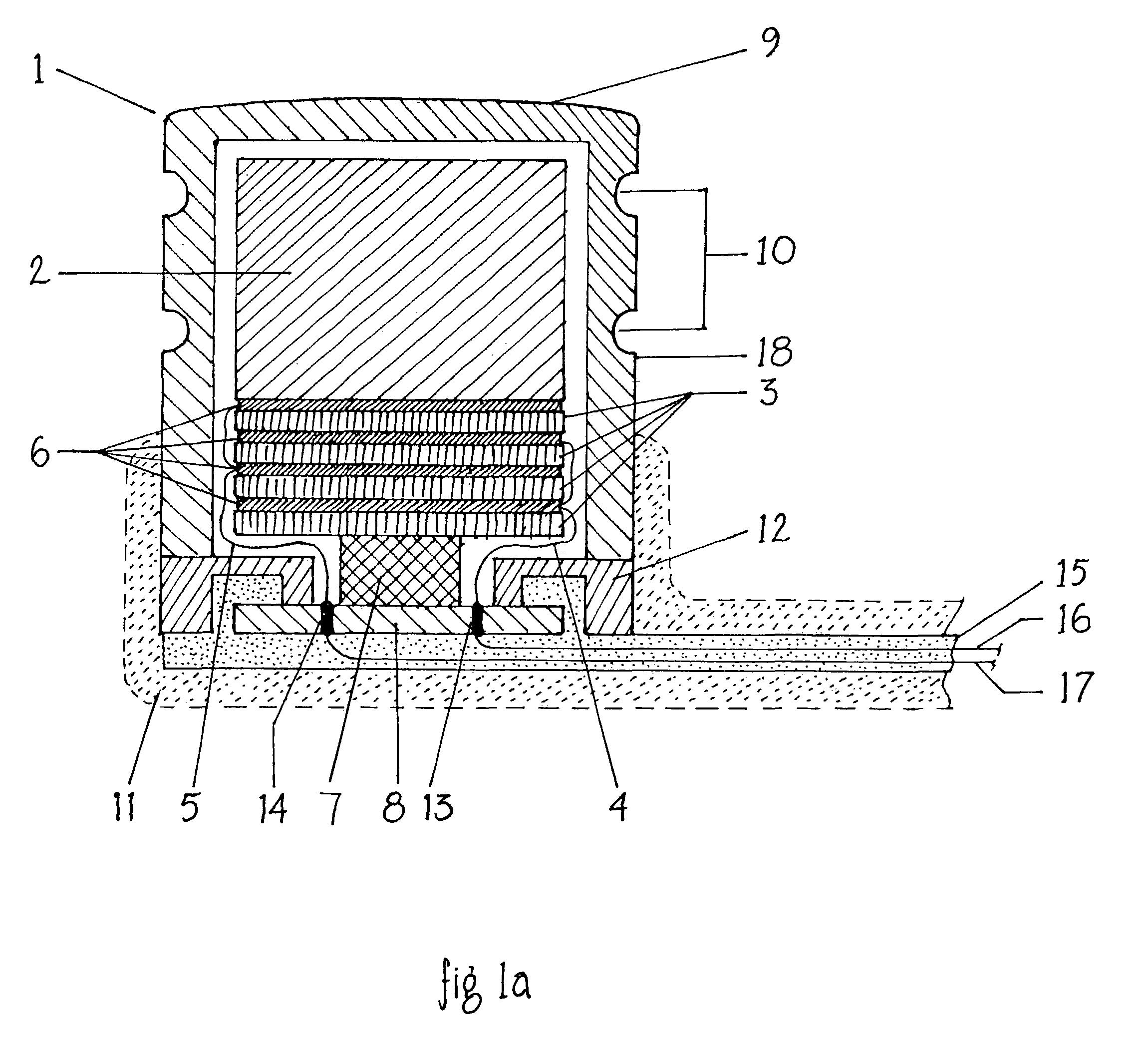
[0025]The inertial mass or masses mounted in the vibrator may be mounted onto and / or between one or more vibrating elements. The hermetic vibrator housing is comprised of a biocompatible material, preferably titanium, or alloys thereof, and is substantially cylindrical in shape. The housing may contain one or more ridges and / or grooves that are radially or spirally disposed along one end of the outside cylindrical wall of the housing to help it securely osseointegrate within bony structure, preferably between the lateral and superior semicircular canals. The other end of the housing is coated with a substantially compliant material, such as silicone, to create an impedance mismatch between the coated housing area and surrounding bone.
[0030]Another aspect to this invention is the implanted microphone. In the preferred embodiment, the microphone is enclosed in a hermetic housing and adapted to be implanted subcutaneously in bone and / or cartilage, substantially near the cymba concha of the auricle, as part of a semi or fully implantable hearing device. At least part of the housing encapsulating the microphone contains one or more circular and / or spiral grooves around its outside wall in order to aid osseointegration with the surrounding bone. Furthermore, at least part of the housing is coated with a compliant material, such as silicone, to increase the impedance to acoustic waves between the microphone housing and the surrounding bone and tissue.
[0032]Yet a further aspect of the invention is the method of implantation of the hearing device in the desired location in the vicinity of the semicircular canals or vestibule. According to one embodiment, the invention is a surgical method, adapted to implant a vibrator substantially between and / or among the semicircular canals and / or vestibule without breaching said canals or vestibule, comprising the steps of forming an approximate two inch incision in the postauricular skin crease and exposing the surface of the mastoid bone, drilling through the mastoid until the antrum is found, thinning the posterior canal wall, identifying the horizontal canal and drilling out a cavity superior to it and recessing the cavity and packing the housing of said device into said cavity using bone paste so as to promote osseointegration.

Problems solved by technology

As a result, these devices can stigmatize the wearer and therefore lead to device rejection.
Although it is reported that the BAHA provides a satisfactory percept in appropriately selected patients (e.g., Lustig et al., “Hearing Rehabilitation Using the BAHA Bone-Anchored Hearing Aid: Results in 40 Patients”, Otology and Neurotology 22:328-34, 2001), it has the significant disadvantages of poor aesthetics and infection / inflammation around the implantation site.
Stenfeldt's thesis provides very limited information about the implanted bone conductor; he does not provide any engineering designs, calculations, or suggestions as to how such devices could be fabricated.
The WO 01 / 93635 device is also preferably electromagnetic and is therefore incompatible with magnetic resonance imaging (MRI).
Most of the prior art describing fully implantable hearing aids and / or tinnitus maskers (e.g., U.S. Pat. Nos. 5,800,336; 5,558,618; 6,277,148; 5,360,388; 5,277,694; 5,772,575) have the fundamental and serious disadvantage that the surgery required for implantation of the electromechanical transducer requires mechanical manipulations on the ossicular chain or directly at the entry area of the inner ear (oval or round window) and thus involves considerable risk of middle or inner ear impairment.
Furthermore, the necessary surgical opening of a sufficiently large access to the middle ear from the mastoid can involve the serious risk of facial nerve damage and the associated partial paralysis of the face.
Moreover, it cannot be guaranteed that the mechanical coupling will be of a long term, stable nature or that additional clinical damage will not occur (e.g., pressure necroses in the area of the ossicles).
Possible surgical complications of this procedure include excessive leakage of perilymph fluid, rupture of the membranous labyrinth, and serious infection of inner ear fluids.
U.S. Pat. No. 6,251,062 suffers from the same disadvantage as other implantable hearing aids / tinnitus maskers in that it relies on the middle ear space for transmission of sound to the inner ear.
Even with optimal acoustic amplification, speech understanding often remains very poor (monosyllabic understanding <30-40%) for these individuals.
The prior art, describing cochlear prostheses, does not appear to allow for a totally implanted hearing aid in addition to the totally implanted cochlear prosthesis.

Method used


Image

  • Totally implantable hearing prosthesis
  • Totally implantable hearing prosthesis
  • Totally implantable hearing prosthesis

Examples


Embodiment Construction

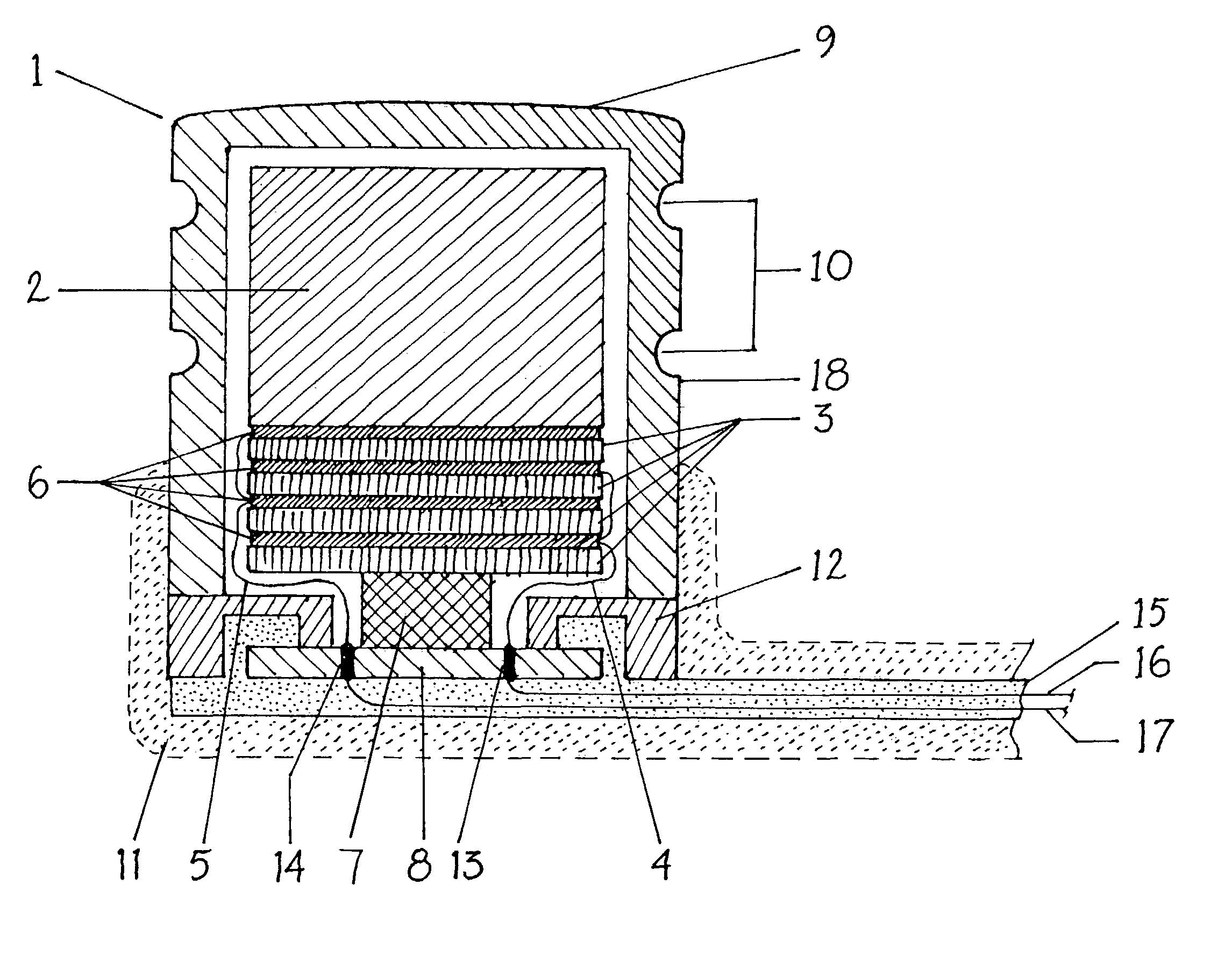
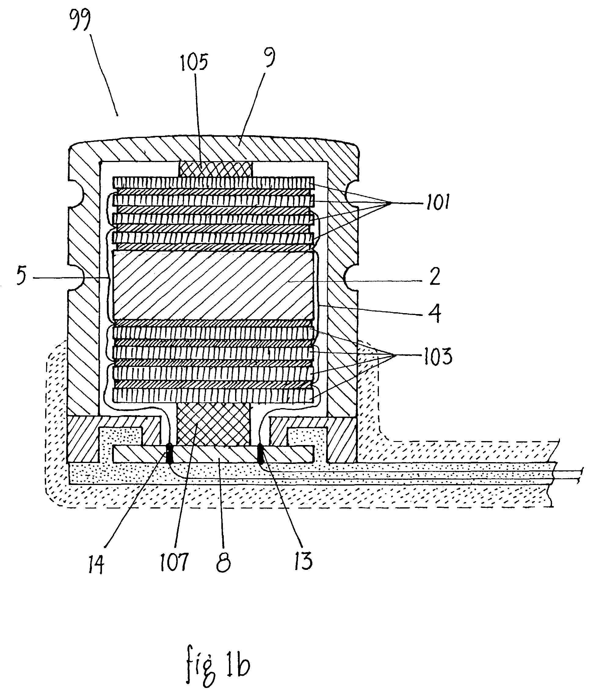
[0057]FIG. 1A shows a cross sectional view of the preferred embodiment of the hermetically sealed inertial mass vibrator 1. The transducer is comprised of a plurality of elements as follows: an inertial mass 2, a stack of piezoelectric elements 3 electrically connected together by wires 4 and 5, with a conductive bond layer 6 between the piezoelectric elements, an interface element 7 connecting the piezoelectric elements to a non-conductive insert 8, a hermetic housing 9 containing an osseointegration end with rings 10, an end coated with a compliant material 11, a base ring 12 with pins 13 and 14 penetrating a non-conductive insert 8 bonded to the base ring 12, with a bioinert cable 15 containing electrical conductors 16 and 17 electrically connected to pins 13 and 14.

[0058]The hermetic housing 9 is comprised of a bioinert material such as titanium, or alloys thereof, with substantially cylindrical walls 18, with one end sealed 9 and the other end coated with a compliant material 1...


PUM


Abstract

The invention comprises a totally implantable hearing prosthesis for hearing impaired persons. An inertial vibrational element is hermetically sealed and implanted in bone between the lateral and superior semicircular canals without breaching the integrity of the canals. The vibrational element is adapted to vibrate the walls of the canals and the fluids contained therein, thereby vibrating contiguous fluids within the cochlea thus stimulating hair cells and creating a hearing percept. The invention can also be adapted to be a tinnitus masking system, and / or used in combination with a cochlear implant hearing system.

Description

FIELD OF THE INVENTION[0001]This invention relates to an implantable prosthesis for use in a hearing system to treat hearing loss, tinnitus, or a combination of hearing loss and tinnitus.BACKGROUND OF THE INVENTION[0002]Hearing loss affects over 10% of the North American population, with over 8% of this group suffering from profound deafness. Tinnitus, described as “hissing, roaring or ringing” in the ear(s) or head, is an auditory perception not produced by an external sound. In the US, as many as 50 million people are affected by tinnitus to some degree and up to 12 million have sought medical attention for the problem. About 1 million sufferers are so seriously debilitated that they cannot function on a normal, day-to-day basis.[0003]Hearing aids, cochlear implants, and tinnitus maskers can be used to help individuals with mild to severe hearing loss, severe to profound deafness, and tinnitus, respectively. By amplifying environmental sounds, hearing aids and cochlear implants of...

Claims


Application Information

Patent Timeline
Patent Type & Authority Patents(United States)
IPC IPC(8): H04R25/00A61N1/36
CPCA61N1/36032H04R25/606H04R2225/31H04R2225/67A61N1/36038
Inventor BERRANG, PETERMIRANDA, TERENCEBOOTH, IAN
Owner MED EL ELEKTROMEDIZINISCHE GERAETE GMBH
Learn More