
Clip device for endoscope and clip for endoscope for use therein

Inactive Publication Date: 2005-03-03
SUMITOMO BAKELITE CO LTD
View PDF7 Cites 209 Cited by
  • Summary
  • Abstract
  • Description
  • Claims
  • Application Information

AI Technical Summary

Benefits of technology

[0008] An object of the present invention is to provide a clipping device which improves defects that the clip can not be again opened once the clip is closed, and that it is necessary to execute the operation in a state in which the clip is not sufficiently opened.
[0009] Further, another object of the present invention is to provide a method of easily mounting the clip so as to shorten a mounting time.

Problems solved by technology

However, since this structure can only press out the fastening device to the front side, there is a defect that the clip can not be opened once the clip is closed.
Further, in order to make the clip to open to the maximum, it is necessary to stop the fastening device just before the crossing portion of the clip, however, it is hard to adjust a position the fastening, device due to a sliding resistance of the fastening device, so that there is a case that the fastening device passes a point where the clip is opened to the maximum, and it is necessary to execute the operation under a state in which the clip is not sufficiently opened.
However, since the clip device executes the opening and closing operation on the basis of a series of operations of pulling the release cord, the clip can not be returned to the state before entering into the crossing portion in the case that the crossing portion of the clip once enters into the fastening device.
In other words, the clip device has a defect that the once closed clip can not be again opened.
Further, in order to open the clip to the maximum, it is necessary to stop the fastening device just before the crossing portion of the clip, however, it is impossible to adjust the position due to the sliding resistance of the fastening device, and the fastening device passes the point where the clip is opened to the maximum, so that there is a case that it is necessary to execute the operation in a state in which the clip is not sufficiently opened.
Since the clip is fixed in a state in which a base end portion of the clip is engaged with a hook provided in the clip device, it is necessary to execute a complicated operation of applying the clip to the hook while gripping the clip by one hand at a time of mounting, so that an operator who is not accustomed to this operation requires a lot of time for this operation.

Method used


Image

  • Clip device for endoscope and clip for endoscope for use therein
  • Clip device for endoscope and clip for endoscope for use therein
  • Clip device for endoscope and clip for endoscope for use therein

Examples


Embodiment Construction

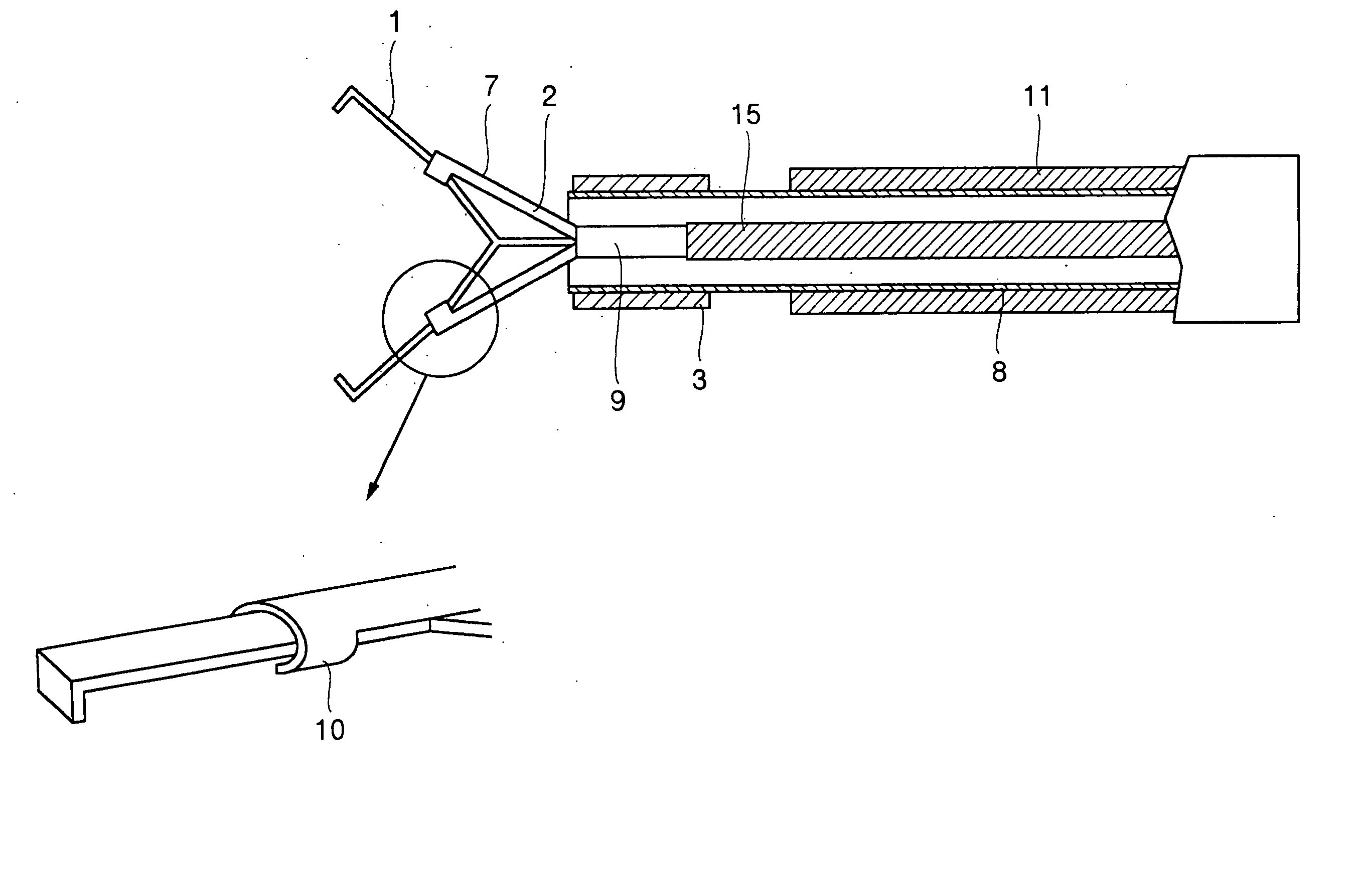
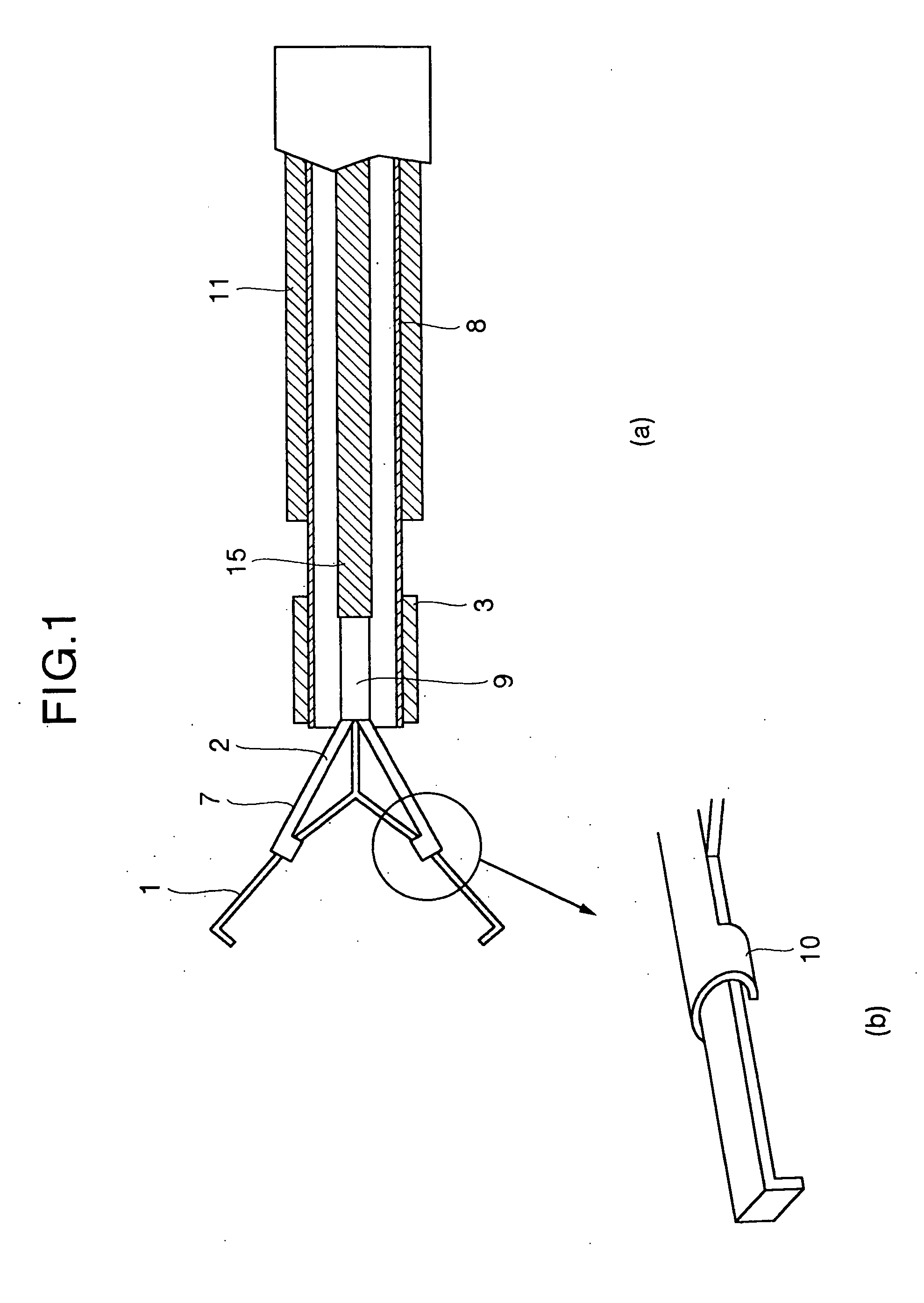
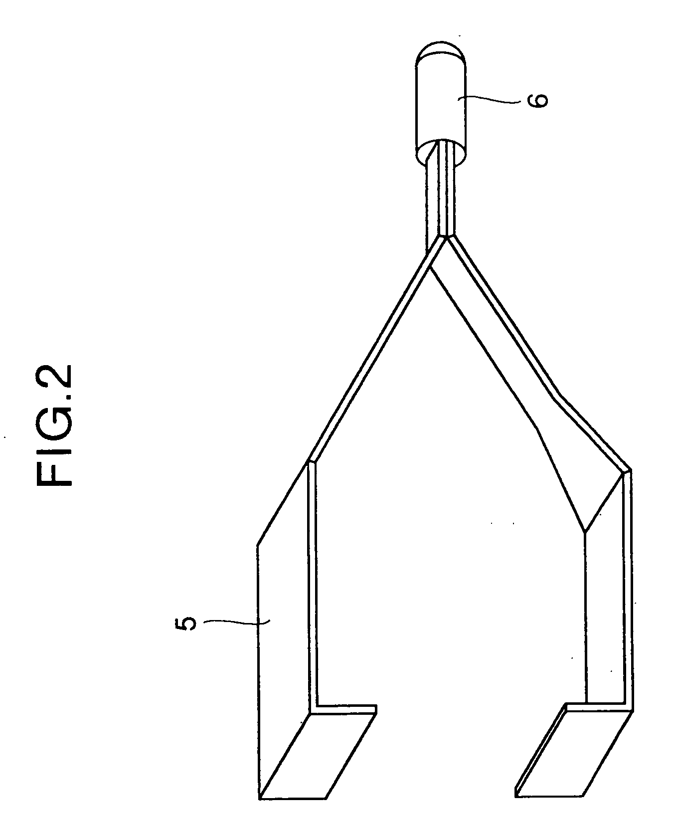
[0046] A description will be in detail given below of the present invention by using embodiments. FIGS. 1(a) and 1(b) are views showing a clipping device for an endoscope corresponding to an embodiment in accordance with the present invention, in which FIG. 1(a) is a general view and FIG. 1(b) is an enlarged view of a connection portion between a clip and an operating means. FIG. 2 is a view showing an embodiment of the clip, and FIGS. 3(a) and 3(b) are views showing another embodiment of the operating means in accordance with the present invention, in which FIG. 3(a) shows a state in which the clip is closed, and FIG. 3(b) shows a state in which the clip is opened. FIG. 4 is a view showing a state in which the clip and the fixing means are set to a plate. FIG. 5 is a cross sectional view of the plate at a time when the clip and the fixing means are set to the plate, and FIGS. 6(a) to 6(d) are views for describing a method of mounting a clip to a clip device for an endoscope in acco...


PUM


Abstract

A clipping device improves defects that the clip can not be again opened once the clip is closed, and that it is necessary to execute the operation in a state in which the clip is not sufficiently opened. The invention provides a clip device for an endoscope constituted by a clipping means having a pair of arm portions which are allowed to be opened and closed, an operating means for holding the arm portions of the clipping means so as to open and close the arm portions, a fixing means for fixing the arm portions after closing the arm portions, and an arranging means for arranging the fixing means in an outer side of the arm portion.

Description

TECHNICAL FIELD [0001] The present invention relates to a clip device for an endoscope. The present invention relates to a clip device used for a marking or the like for clarifying an area to which a ligature or resection treatment is applied in a bleeding portion in a biological tissue, for example, under an endoscopic treatment, and a clip used for the clip device. PRIOR ART [0002] A method of ligating the bleeding portion by introducing a clip in an endoscopic manner is much applied to the bleeding within a body cavity, however, such a clip is disclosed, for example, in JP-U-53-20957. This invention is constituted by a clip in which a pair of clamping pieces are connected in a rear end and are crossed to each other in an intermediate portion and an inclined surface is formed in each of front and rear outer surfaces of the crossing portion, and a fastening device which is slid on the inclined surface of the clip so as to open and close the clip, and an introduction device for slid...

Claims


Application Information

Patent Timeline
IPC IPC(8): A61B17/064A61B17/08A61B17/10A61B17/122A61B17/128A61B17/30
CPCA61B17/0643A61B17/083A61B17/10A61B17/30A61B17/122A61B17/1222A61B17/1285A61B17/105
Inventor MASUDA, HARUHIKOHARADA, SHINETSU
Owner SUMITOMO BAKELITE CO LTD
Learn More