
Hinge module and electronic device

Active Publication Date: 2019-10-17
COMPAL ELECTRONICS INC
View PDF18 Cites 3 Cited by
  • Summary
  • Abstract
  • Description
  • Claims
  • Application Information

AI Technical Summary

Benefits of technology

The invention provides a hinge module and an electronic device that can adjust the size of torque to improve the performance of large devices. The hinge module can be used to connect two bodies and has two separate spaces for carrying an assembly. By using a single assembly, the hinge module provides a lower torque so that the two bodies can easily expand or close. However, by using two assemblies, the hinge module provides a higher torque so that the two bodies can be held securely. The number of assemblies can be adjusted based on the characteristics and torque demands of the two bodies. The hinge module can meet standard torque demands while reducing overall thickness.

Problems solved by technology

However, the currently available hinge modules have torque values that are unadjustable and thus, are not suitable for being applied to notebook computers for different demands.
Thus, the currently available hinge modules have to be operated with the notebook computers of specific specifications and are restricted in manufacturing flexibility.
In addition, the currently available hinge modules are usually configured to connect the bodies at one single side, causing the hinge module to receive an uneven force while the single-side connection mechanism has a large volume, which is unfavorable for the target of notebook computer miniaturization.

Method used


Image

  • Hinge module and electronic device
  • Hinge module and electronic device
  • Hinge module and electronic device

Examples


Embodiment Construction

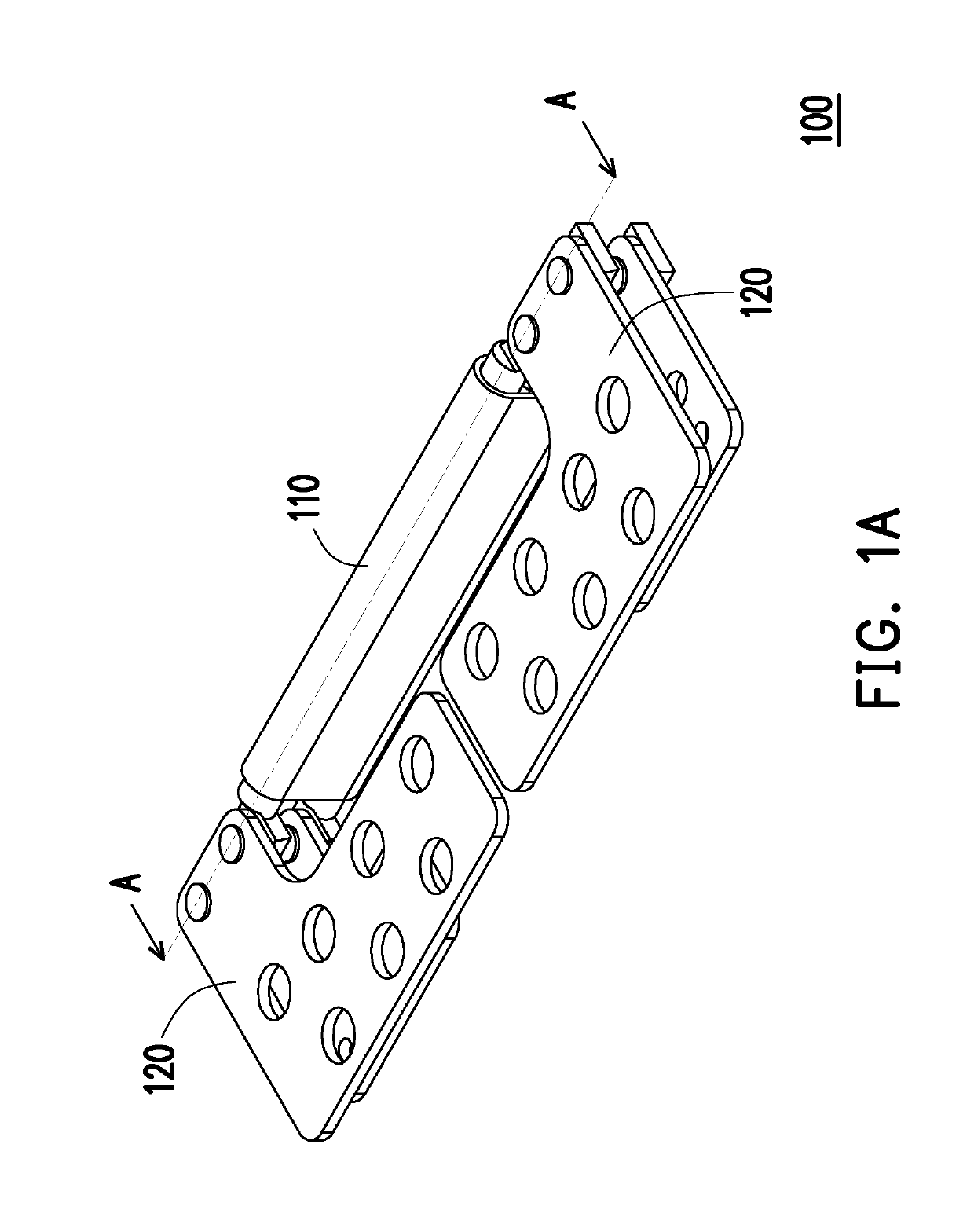
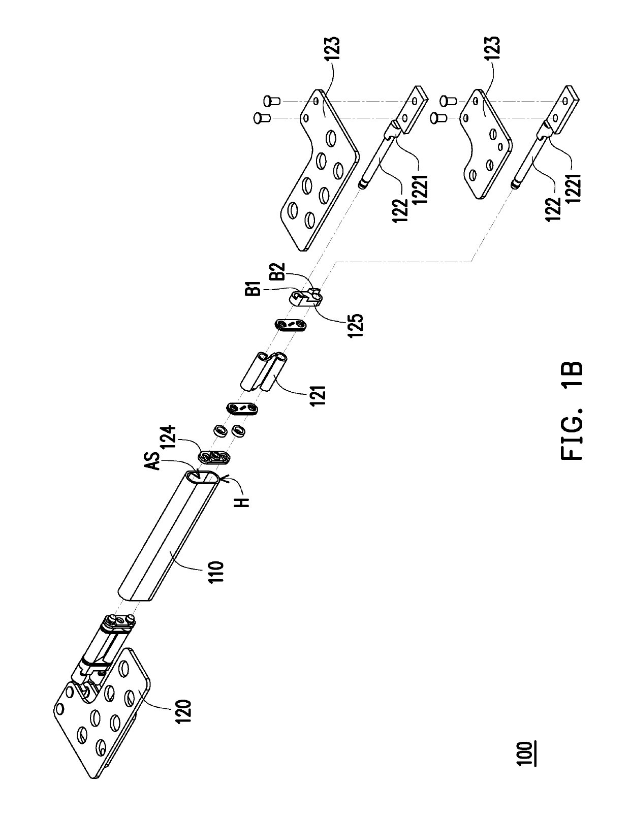
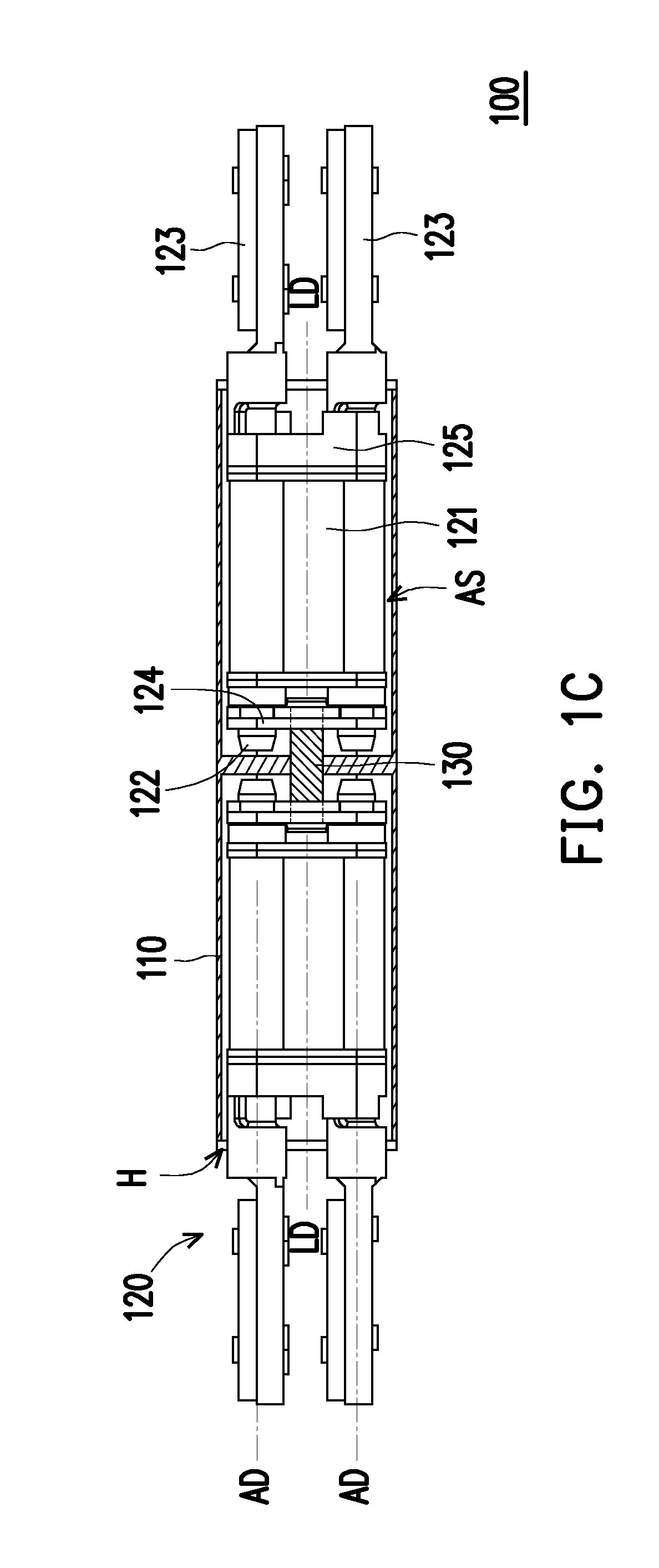
[0020]FIG. 1A is a schematic perspective diagram illustrating a hinge module according to an embodiment of the invention. FIG. 1B is a schematic exploded diagram of the components of the hinge module depicted in FIG. 1A. FIG. 1C is a schematic cross-sectional diagram illustrating the hinge module depicted in FIG. 1A along line A-A.

[0021]Referring to FIG. 1A to FIG. 1C, a hinge module 100 of the present embodiment includes a housing 110 and at least one carrying assembly 120. The housing 110 includes two accommodation spaces AS. The at least one carrying assembly 120 is, for example, one and disposed at the housing 110. The carrying assembly 120 includes a torque element 121, two rotation shafts 122 and two brackets 123.

[0022]The two accommodation spaces AS respectively have openings H which are respectively formed at two opposite sides of the housing 110. The torque element 121 is disposed in one of the accommodation spaces AS. The two rotation shafts 122 pass through the torque ele...


PUM


Abstract

A hinge module includes a housing and at least one carrying assembly. The housing includes two accommodation spaces. The at least one carrying assembly is disposed at the housing and includes a torque element, two rotation shafts and two brackets. The torque element is disposed in one of the accommodation spaces. The two rotation shafts pass through the torque element. The two brackets are respectively connected to the two rotation shafts and located outside the housing. Each bracket is adapted to rotate along with the corresponding rotation shaft and rotate relative to the torque element.

Description

CROSS REFERENCE TO RELATED APPLICATION[0001]This application claims the priority benefit of U.S. provisional application Ser. No. 62 / 656,988, filed on Apr. 13, 2018. The entirety of the above-mentioned patent application is hereby incorporated by reference herein and made a part of specification.FIELD OF THE INVENTION[0002]The application relates to a hinge module and an electronic device and more particularly, to a hinge module capable of adjusting a torque size and an electronic device.DESCRIPTION OF RELATED ART[0003]Generally, a hinge module is disposed between a system body and a display body of a notebook computer, such that the system body and the display body may be expanded or closed relative to each other through the hinge module. Generally, through a torque of the hinge module, the system body and the display body may be adjusted to any angle. However, the currently available hinge modules have torque values that are unadjustable and thus, are not suitable for being applie...

Claims


Application Information

Patent Timeline
IPC IPC(8): G06F1/16F16C11/04E05D3/12E05D11/06E05D11/08
CPCE05D11/06E05Y2201/224E05D3/12G06F1/1683E05Y2900/606E05D11/082G06F1/1681F16C11/04G06F1/1616F16C11/103E05Y2999/00
Inventor LIN, CHE-HSIENCHU, CHE-HSIENSHEN, CHUN-AN
Owner COMPAL ELECTRONICS INC
Learn More