
Large area catch basin filter

a catch basin and filter technology, applied in the direction of sewage draining, separation processes, ways, etc., can solve the problems of affecting the effect of sewage discharge, waste of resources, and waste of resources, and achieve the effect of simple and economical installation, transportation and installation

Inactive Publication Date: 2005-03-10
NINO KHALIL IBRAHIM
View PDF83 Cites 32 Cited by
  • Summary
  • Abstract
  • Description
  • Claims
  • Application Information

AI Technical Summary

Benefits of technology

[0014] An object of the present invention is to provide an apparatus that minimizes the volume of trash that is permitted to pass through a catch basin
[0021] Another object of the present invention is to provide such an apparatus that can be installed using readily-available and effective means for connecting it to the catch basin and for connecting its components to one another.

Problems solved by technology

When the trash enters into the extended drainage system, it tends to become lodged and to block or retard all or a significant part of the fluid volume, ultimately causing the incoming fluid to accumulate in and ultimately flood the street or highway.
In order to minimize such occurrences of flooding, it is necessary to expend considerable effort and cost to remove the lodged trash from the downstream portions of the drainage system.
It may be observed that most curb inlets and surface grates have no effective means for blocking the entry of trash.
But typically those devices cover a relatively small area within the catch basin and have a relatively small capacity for retaining trash before they overflow (along with any incoming trash).
Thus, the existing (generally small capacity) catch basin trash filters have not been able to fully resolve the problems of retaining large amounts of trash, avoiding significant interference with the volume of fluid flowing into the drainage system, and maintaining an unobstructed catch basin inlet opening for possible installation therein of other trash impeding devices.
Very little protection is afforded by the existing catch basin filters against trash clogging the drainage system during incidents of large amounts of fluid (and trash carried with the fluid) entering the catch basin.

Method used


Image

  • Large area catch basin filter
  • Large area catch basin filter
  • Large area catch basin filter

Examples


Embodiment Construction

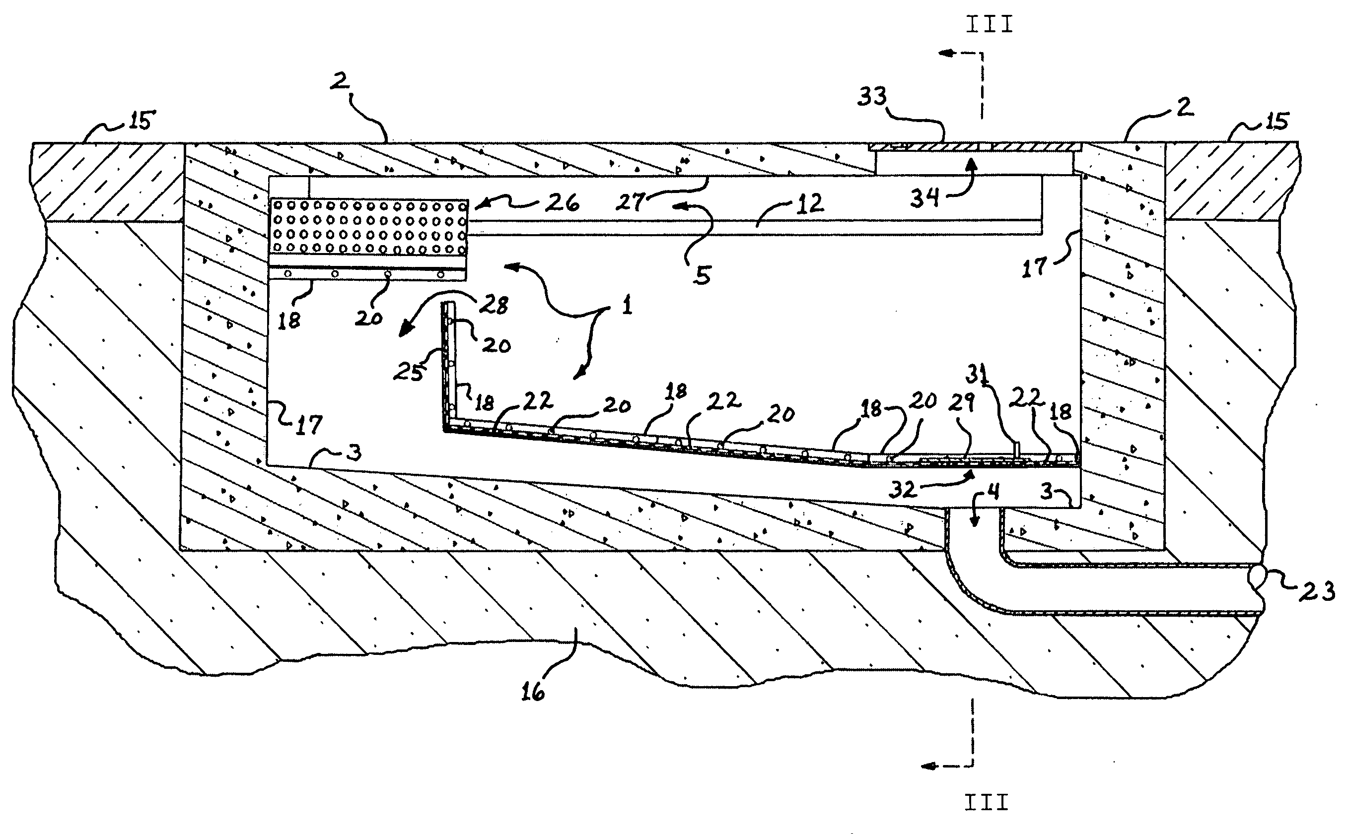
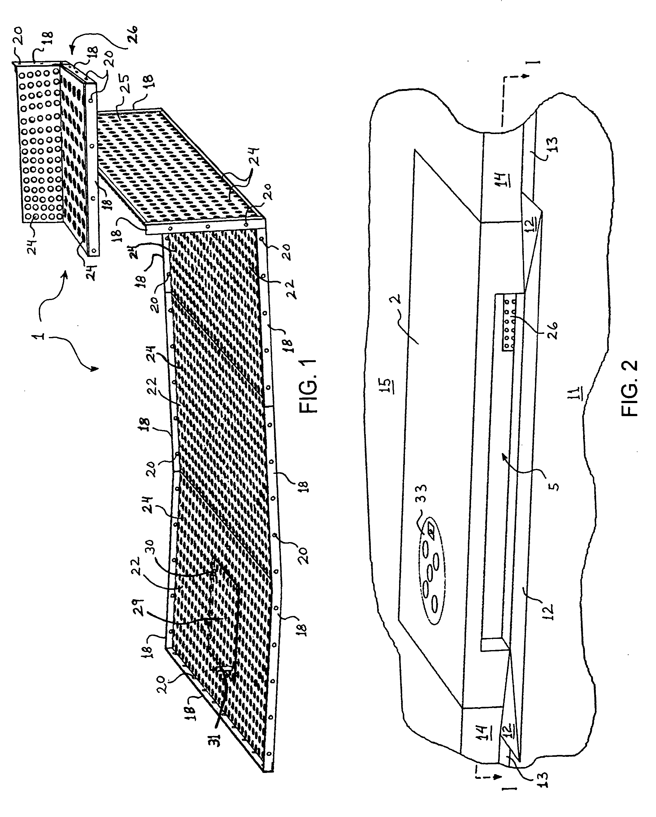
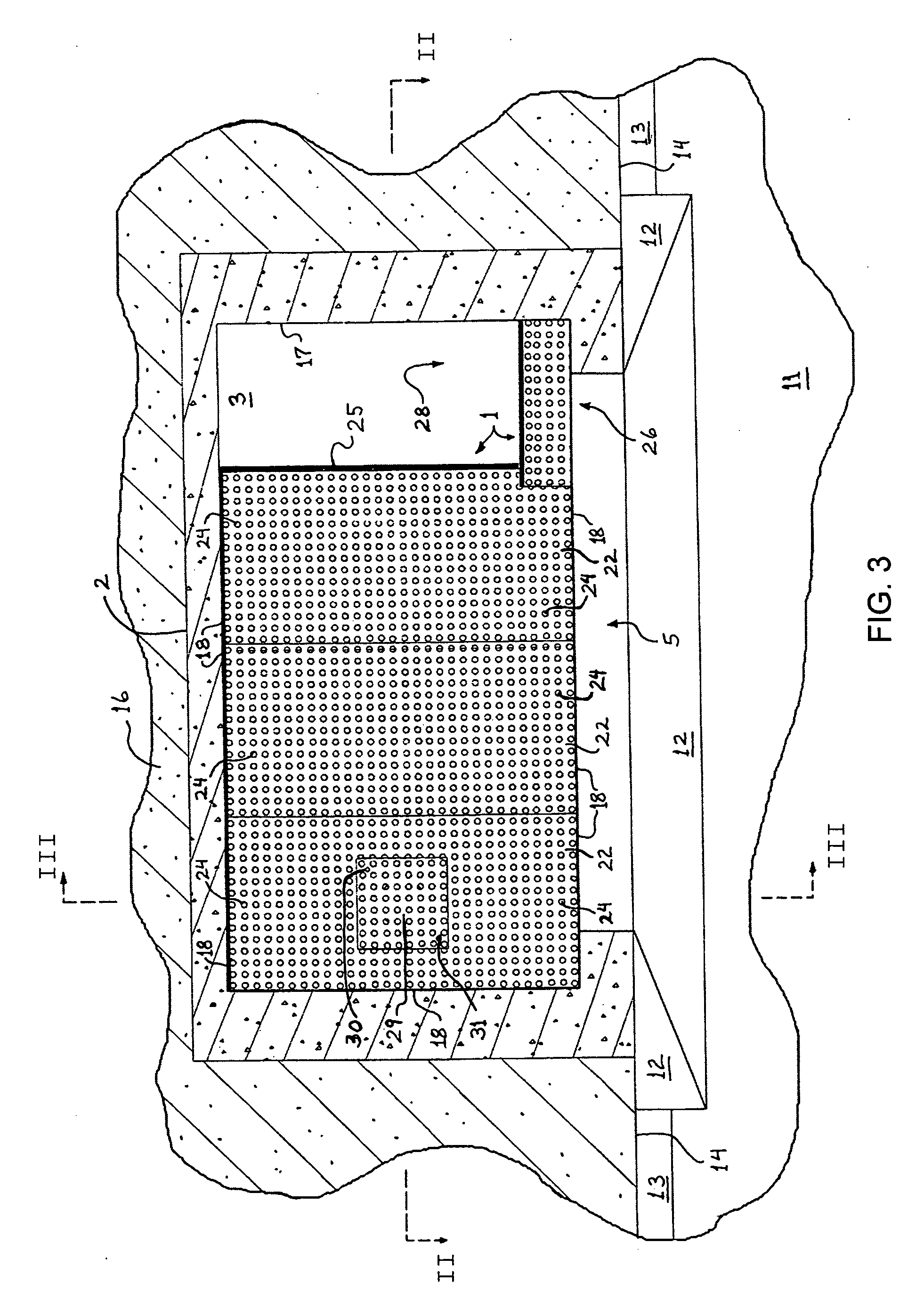
[0038] As used throughout this specification, unless expressly stated otherwise, the following terms have the definitions referred to or specified in this paragraph. The term “apparatus” is used as a generic term meaning any physical embodiment of the present invention. The term “embodiment” means embodiment of the apparatus. The term “trash” has the meaning given to it in the BACKGROUND OF THE INVENTION section, with the predetermined size being whatever size of trash the user of the apparatus wishes to prevent from passing to the downstream side of the installed apparatus (with due consideration to the fact that some trash that is non-rigid or that has a dimension smaller than the predetermined size might not be blocked). The term “the user” includes any person or organization having responsibility for making a decision on behalf of a current or prospective user of the apparatus, with regard to the particular issue presented herein for consideration by the user. The term “fluid” h...


PUM

PropertyMeasurementUnit
Fractionaaaaaaaaaa
Sizeaaaaaaaaaa
Areaaaaaaaaaaa

Abstract

The present invention relates to an apparatus for maximizing the blockage of fluid borne solid materials from passage through a catch basin into the downstream parts of a fluid flow channel, with minimum impact on the volume and rate of fluid passing through the channel. The apparatus comprises at least one filter sheet secured within the catch basin at a location above and covering a large proportion of the floor of the catch basin, an overflow wall separating the filter area from an unfiltered overflow area, and a diverter for directing incoming trash away from the overflow area and to the filter side of the overflow wall. Although the apparatus covers a large area within the catch basin, the overflow wall, overflow area, and clearance between the filter sheet(s) and the floor provide sufficient space for fluid and excess trash to pass in the event the capacity of the apparatus for holding them is exceeded. Preferably, the apparatus also has a drain-access hole through the filter sheet(s) and a movable hole cover located appropriately to facilitate access to the catch basin drain.

Description

CROSS-REFERENCE TO RELATED APPLICATIONS [0001] This application is derived from U.S. Provisional Application No. 60 / 500,842, filed Sep. 4, 2003, and claims priority based upon the filing date of said Provisional Application.BACKGROUND OF THE INVENTION [0002] The present invention relates to an apparatus for installation into a drainage catch basin or similar structure (referred to herein simply as catch basin) for blocking the passage of solid materials that enter the catch basin while permitting the passage of fluid into the downstream elements of the drainage system, such as a drainage pipe or other channel. More particularly, the present invention relates to such an apparatus that also permits the overflow of fluid and excess accumulation of solid materials under circumstances wherein the flow of fluid and possibly additional solid materials into the catch basin exceeds the capacity of the apparatus. [0003] As used in this specification, “solid material” means any item of natural...

Claims


Application Information

Patent Timeline
IPC IPC(8): E03F1/00
CPCE03F5/0404E03F1/00
Inventor NINO, KHALIL IBRAHIM
Owner NINO KHALIL IBRAHIM
Features
  • Generate Ideas
  • Intellectual Property
  • Life Sciences
  • Materials
  • Tech Scout
  • Unparalleled Data Quality
  • Higher Quality Content
  • 60% Fewer Hallucinations
Learn More