Method and device for braking a motor

Inactive Publication Date: 2005-03-10
BLACK & DECKER INC
View PDF41 Cites 81 Cited by
  • Summary
  • Abstract
  • Description
  • Claims
  • Application Information

AI Technical Summary

Problems solved by technology

This technique presents a number of problems.
It results in very high currents during braking.
It may also result in demagnetization of the field magnet as well as accelerating brush wear.
It also results in sudden braking, which can be detrimental to the life of the tool transmission.
This approach also presents problems.
The power resistors are bulky and generate heat.
Even though the brake currents are lower, the brake times are not controllable by this approach.

Method used


Image

  • Method and device for braking a motor
  • Method and device for braking a motor
  • Method and device for braking a motor

Examples


Embodiment Construction

[0027] The following description of the preferred embodiment(s) is merely exemplary in nature and is in no way intended to limit the invention, its application, or uses.

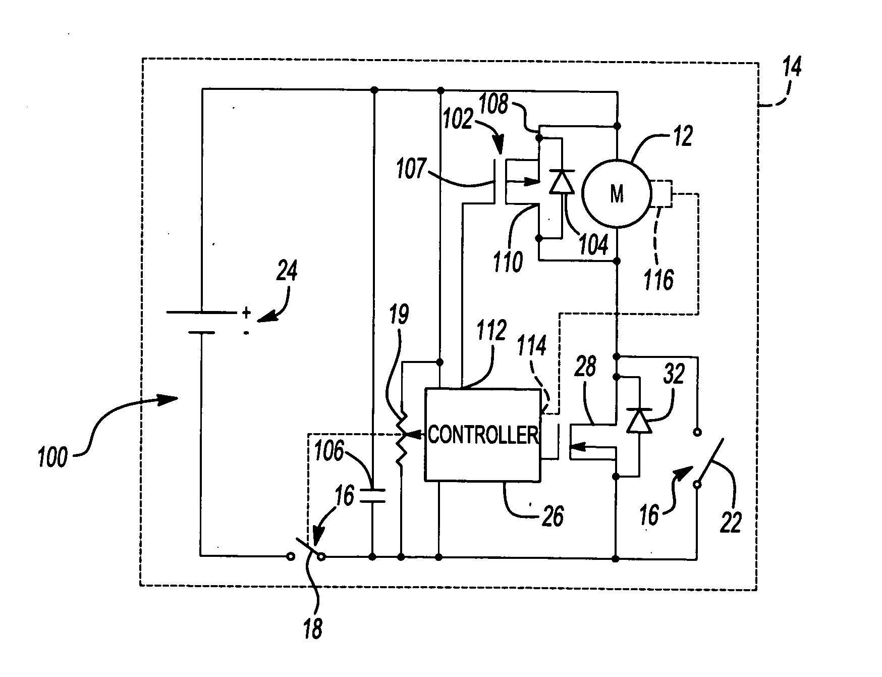
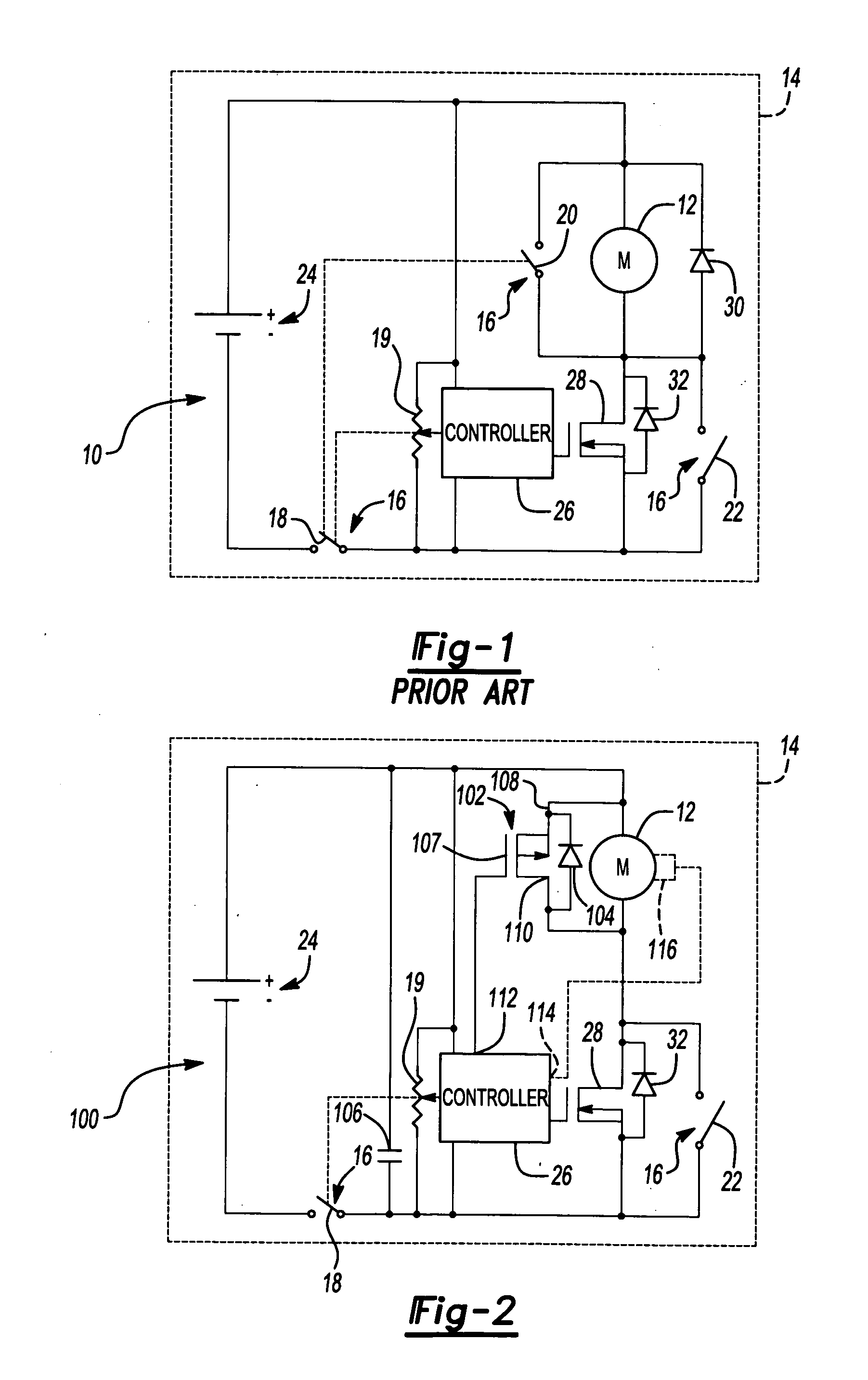
[0028]FIG. 2 shows a motor control circuit 100 for controlling power to a motor 12 that brakes motor 12 in accordance with the invention. Elements in common with FIG. 1 will be identified with like reference numerals and the discussion of motor control circuit 100 will focus on the differences between motor control circuit 100 and motor control circuit 10.

[0029] Motor control circuit 100 has a braking power switching device 102 connecting the motor windings of motor 12 in place of braking contacts 20 of trigger switch 16. Motor control circuit 100 also has a storage capacitor 106 coupled to controller 26. Diode 30 is eliminated.

[0030] Braking power switching device 102 is illustratively a P-channel MOSFET having an internal diode bridging its source and drain, identified as diode 104. Gate 107 of braking power swi...


PUM


Abstract

A method and apparatus for braking a motor has a braking circuit that intermittently shorts the windings of the motor to brake the motor. The braking circuit is powered by back EMF generated by the motor when power is disconnected from the motor.

Description

CROSS-REFERENCE TO RELATED APPLICATIONS [0001] This application is a continuation-in-part of U.S. patent application Ser. No. 10 / 647,807 filed on Aug. 25, 2003, which claims the benefit of U.S. Provisional Application No. 60 / 419,352 filed Oct. 18, 2002.FIELD OF THE INVENTION [0002] The present invention relates to motor braking, and more particularly, to braking a DC motor in power tools. BACKGROUND OF THE INVENTION [0003] Braking of a DC motor in a power tool is typically accomplished by closing brake contacts across the motor windings after the trigger of the switch that switches power to the motor windings is released. This technique presents a number of problems. It results in very high currents during braking. It may also result in demagnetization of the field magnet as well as accelerating brush wear. It also results in sudden braking, which can be detrimental to the life of the tool transmission. The brake times are also not controllable. [0004] An alternate approach is to co...

Claims


Application Information

Patent Timeline
IPC IPC(8): H02P3/12H02P3/00H02P3/08H02P3/18
CPCH02P3/12
Inventor CARRIER, DAVID A.GORTI, BHANUPRASAD V.
Owner BLACK & DECKER INC
Why Eureka
Try Eureka