Optical disk recording method, optical disk device and optical disk

a recording method and optical disk technology, applied in the field of optical disks, can solve the problems of high possibility of geometrical mark distortion and mark edge shift, and high possibility of mark edge shift in the waveform of a playback signal, and achieve the effect of convenient operation of optical disk recording method and optical disk devi

Active Publication Date: 2005-03-17
HITACHI CONSUMER ELECTRONICS CORP
View PDF8 Cites 82 Cited by
  • Summary
  • Abstract
  • Description
  • Claims
  • Application Information

AI Technical Summary

Benefits of technology

The invention is an optical disk recording method and device that can accurately record modulation code marks on various recording media without changing the configuration of the basic waveform. This allows for easy compensation of mark edge shift caused by thermal interference during recording and resolving power during reproducing. The invention also provides an easy-to-use optical disk recording device.

Problems solved by technology

The technical problem addressed in this patent text is the occurrence of mark edge shift and geometrical mark distortion in a DVD-RAM when recording information using a recording strategy based on a multi-pulse chain. The problem is caused by the small size of the recording film and the high intensity of the energy beam applied during recording. The text describes a correction technique to address the problem and ensure optimal recording quality. The text also discusses the characteristics of the next-generation optical disk and the challenges in recording information on it.

Method used


Image

  • Optical disk recording method, optical disk device and optical disk
  • Optical disk recording method, optical disk device and optical disk
  • Optical disk recording method, optical disk device and optical disk

Examples


second embodiments

First and second embodiments of the invention will be described below with reference to the drawings.

FIG. 4 shows an optical disk device according to the invention. In FIG. 4, the reference numeral 100 designates an optical disk; 110, a spindle motor; 112, a chucking mechanism; 115, a guide rail; 116, a feed motor; 117, an optical pickup; 121, an objective lens actuator; 131, a semiconductor laser; 132, a collimator lens; 133, a beam splitter; 134, a detection lens; 135, a photo detector; 136, an objective lens; 150, a system controller; 151, a servo controller; 152, an amplifier; 153, a decoder; 154, a signal processing circuit; 155, a delay circuit; 156, current sinks; 157, a constant current source; 158, an output terminal; 159, an input terminal; 160, a power supply terminal; 161, a signal processing circuit; and 170, a binarization circuit.

first embodiment

An optical disk recording method according to the invention will be described.

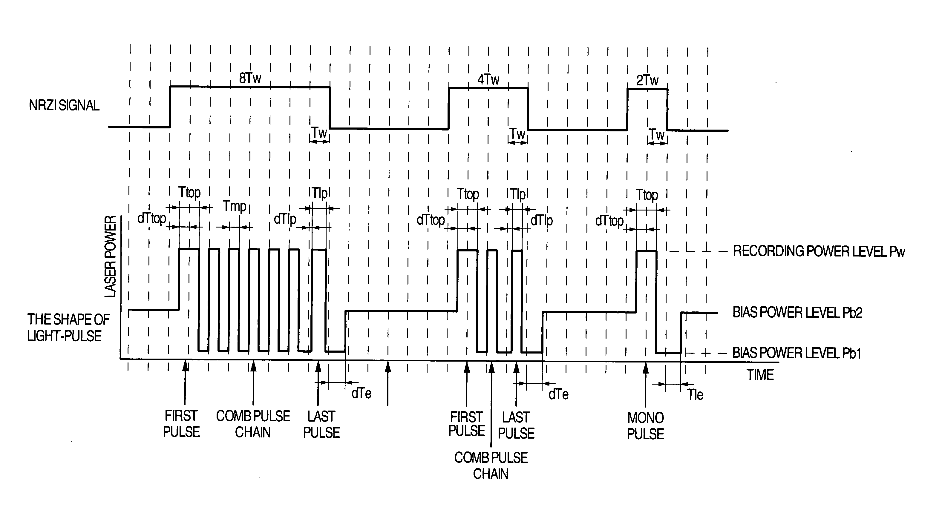
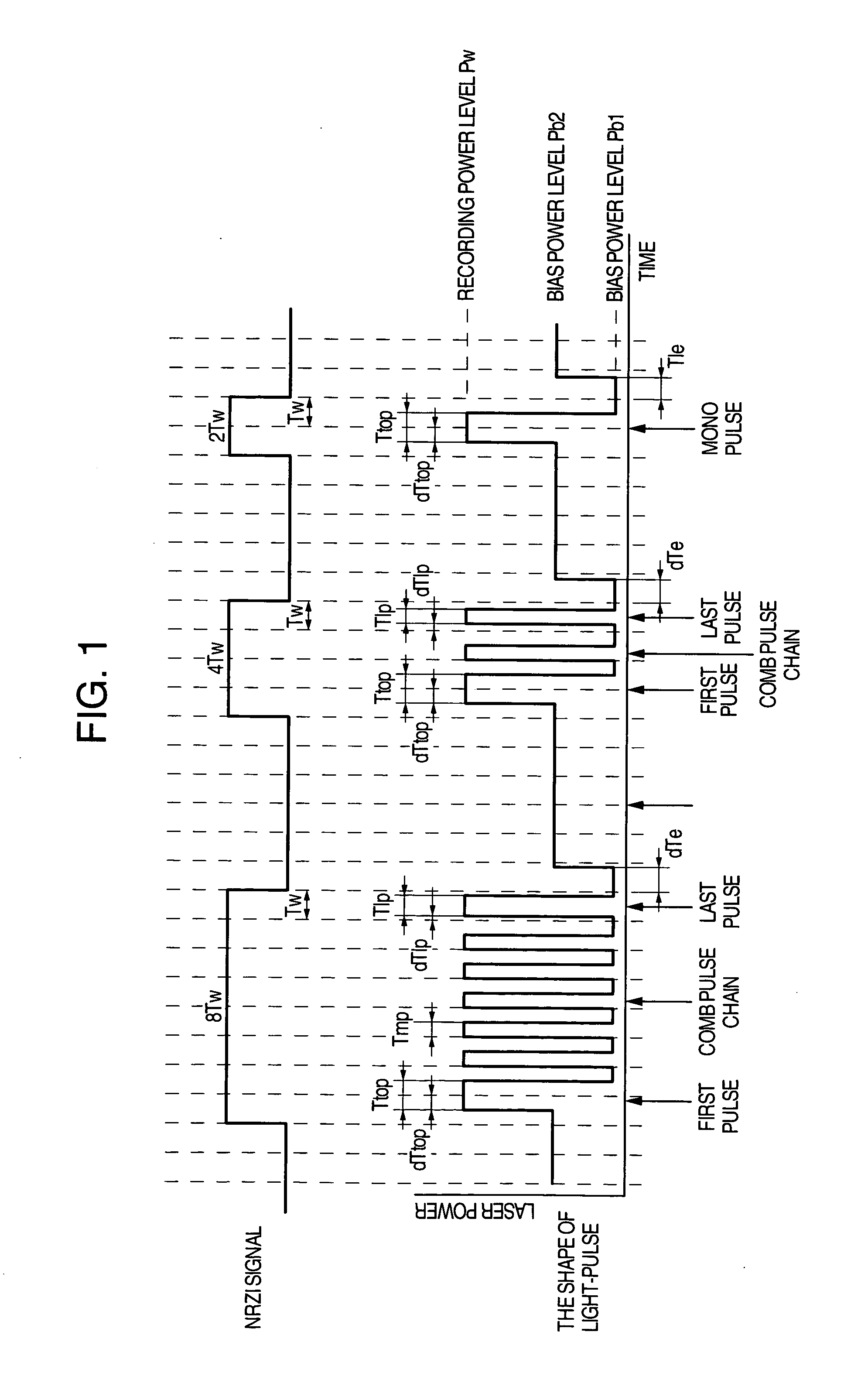
FIG. 1 shows a recording strategy in the optical disk recording method according to the invention. In this embodiment, there is shown the case where information is recorded after converted into RLL(1, 7) as a modulation code. When Tw is the time width (detection window width) of a reference clock pulse for recording and reproducing data, the smallest mark or space length is 2Tw (twice as large as the time Tw) and the largest mark or space length is generally 8Tw.

When an NRZI signal expressing time-series information to be recorded in the optical disk is given, the NRZI signal is converted into a time-series energy beam power level change, that is, an emission pulse waveform by a suitable signal processing circuit.

Three power levels, namely, a recording power level Pw, a first bias power level Pb1 and a second bias power level Pb2, are set on the assumption that a rewritable phase change material having...
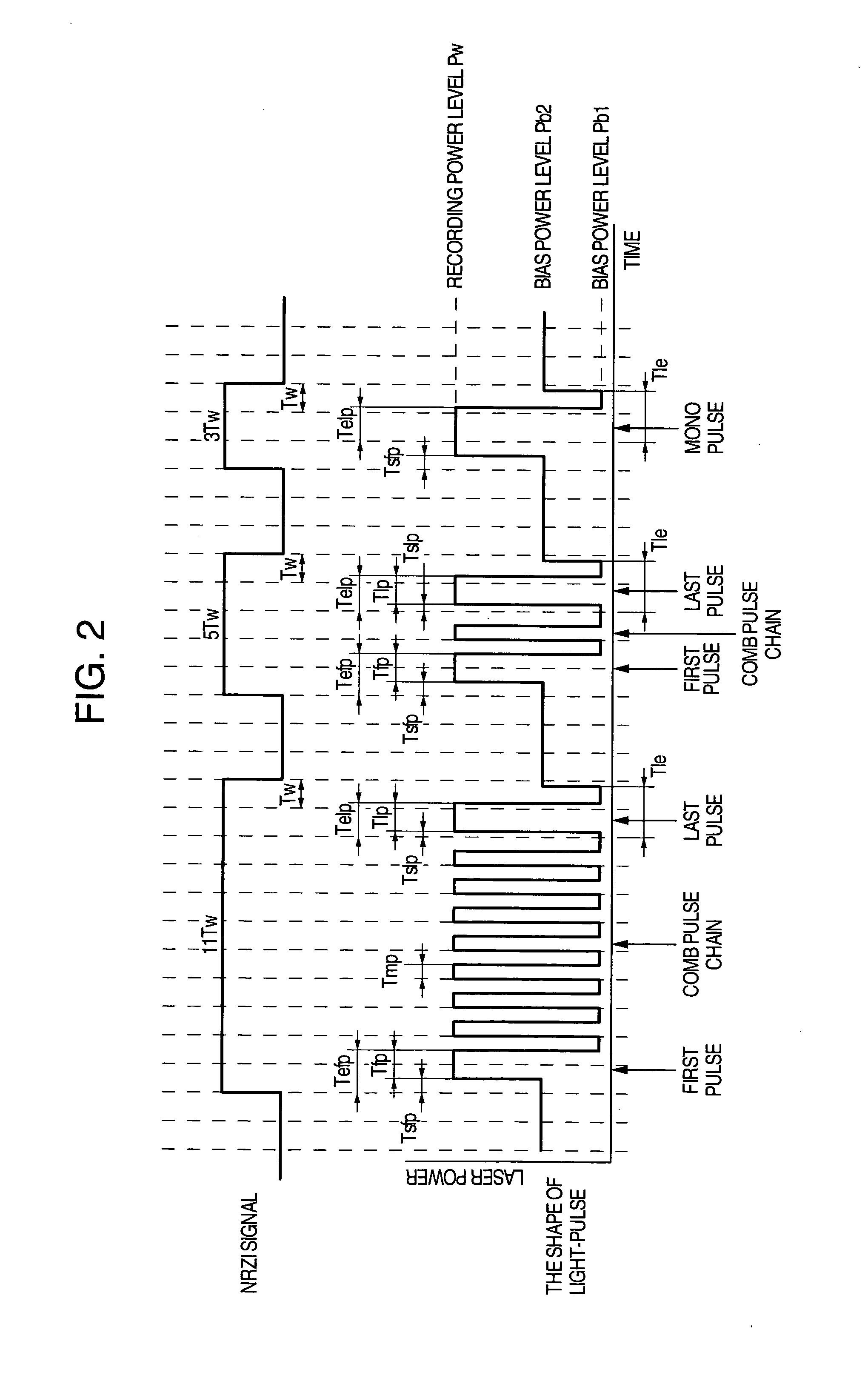
second embodiment

The optical disk recording method as the invention will be described below.

In this embodiment, the time point (position) and irradiation time period (width) of a recording pulse of 2Tw are defined independent of the pulse chain of 3Tw or larger. That is, let dTop2 be the pulse rise position of the recording pulse and let Ttop2 be the irradiation time period of the recording pulse. With respect to dTtop2 and Ttop2, a reference table as shown in FIG. 8 is defined independently in accordance with the combination of the preceding space length and the following space length. Incidentally, a reference table of dTop and Ttop is defined on the basis of the recording mark length of 3Tw or larger.

When the recording pulse of 2Tw is defined by the combination of the preceding space length and the following sapce length as described above, dependence of rear edge shift of a 2Tw mark on the following space length can be compensated though the dependence cannot be compensated in the first embod...


PUM


Abstract

An optical disk recording method includes the steps of: providing a multi-pulse chain from a recording wave; independently changing the pulse rise timing and pulse fall timing (pulse width) of the first pulse in the multi-pulse chain in accordance with a preceding space length and a recording mark length; changing the pulse rise timing and pulse fall timing (pulse width) in accordance with a following space length and the recording mark length in a predetermined timing or in independence; and in relation to the smallest mark recorded by irradiation with mono pulse, changing the rise timing in accordance with the preceding space length and the recording mark length and the fall timing (pulse width) in accordance with the following space length and recording mark length, compensating various optical disks different in recording material without change of the fundamental waveform.

Description


Claims


Application Information

Patent Timeline
Owner HITACHI CONSUMER ELECTRONICS CORP
Why Eureka
Try Eureka