Mold device having a combination of molds for stretch blow molding

a mold and mold technology, applied in the field of mold devices having a combination of molds, can solve the problems of affecting the appearance of the bottle, taking a long time to open or close the main mold, and affecting the labeling, so as to achieve the effect of easy maintenance of the molds' closing sta

Inactive Publication Date: 2005-03-17
A K TECH LAB INC
View PDF11 Cites 20 Cited by
  • Summary
  • Abstract
  • Description
  • Claims
  • Application Information

AI Technical Summary

Benefits of technology

[0009] The present invention is to solve the problem of the conventional blow mold device mentioned above. The object is to provide a novel mold device having a combination of molds for stretch blow molding which prevents the parting line created in pre-blow molding by using a cylindrical pre-blow mold, and even if the pre-blow mold is movable between the main blow mold halves placed on the bed, the mold clamping device for the main blow mold doesn't have to clamp the pre-blow mold, and a bottom mold can be equipped.
[0012] In the construction mentioned above, pre-blow molding can be operated by closing a neck mold and a cylindrical member, which is used as a pre-blow mold, and the pre-blow mold can be opened with moving the cylindrical member downward, so that no parting line is left on the body of the preliminary article formed in pre-blow molding. Moreover, because the size of the cylindrical member can be determined according to the level of pre-blow molding, the size of the cylindrical member won't be too large. The diameter of the cylindrical member fits within the diameter of the neck mold, so the cylindrical member can be more remarkably light and compact than the conventional split mold type, and the stroke of the main blow mold can be shorter. Therefore, the mold device can be smaller.
[0013] Since opening and closing the neck mold and the pre-blow mold are achieved by a lifting device, the mold clamping device is operated only for main blow molding. Consequently, the number of clamping operation is limited to once in a molding cycle, the time for opening and closing as the stroke becomes shorter, and no delay occurs in a molding cycle as a result.
[0014] Closing of the neck mold and the pre-blow mold is achieved by fitting the open end of the cylindrical member and the annular groove provided on the end surface of the neck mold. Thus, closing state of molds can be maintained easily by applying sufficient pressure by the lifting device to withstand the pre-blow molding pressure, and opening action can be achieved by lowering the pre-blow mold by the lifting device. Therefore, an additional mean for opening and closing the molds is not necessary.

Problems solved by technology

Consequently, the longitudinal convex parting line becomes more exaggerated than a parting line on a bottle, which doesn't require pre-blow molding, so it often affects the appearance of the bottle or causes a problem for labeling.
It takes a long time to open or close the main blow molds, and it causes a delay in the molding cycle time including the increase of the number of clamping action.
Furthermore, since the main blow molds are clamped with the pre-blow molds, the pre-blow molds have to be as large as the main blow molds irrelevantly to the substantial requirement for the pre-blow molding even in the pre-blow molding process wherein the preform is stretch blow molded by a little because the pre-blow molds have to be able to press the whole main blow molds.
Besides, the main blow molds can't be opened by itself, so it requires an apparatus for opening the main blow mold with the backward movement of the mold clamping device.
Consequently, the blow molding device tends to be complicated and large.
The problem of the blow mold device mentioned above can't be solved by changing the position of the molds by placing the main blow molds on the bed and the pre-blow molds under the main blow molds as long as a pair of split molds is adopted for the pre-blow molds.
Also, if the pre-blow molds are movable between the split main blow mold halves, it is difficult to place a bottom mold for the main blow mold, and the usage of the main blow mold is limited to a mold for a container having a flat bottom, which is removable with the opening by the main blow mold.

Method used


Image

  • Mold device having a combination of molds for stretch blow molding
  • Mold device having a combination of molds for stretch blow molding
  • Mold device having a combination of molds for stretch blow molding

Examples


Embodiment Construction

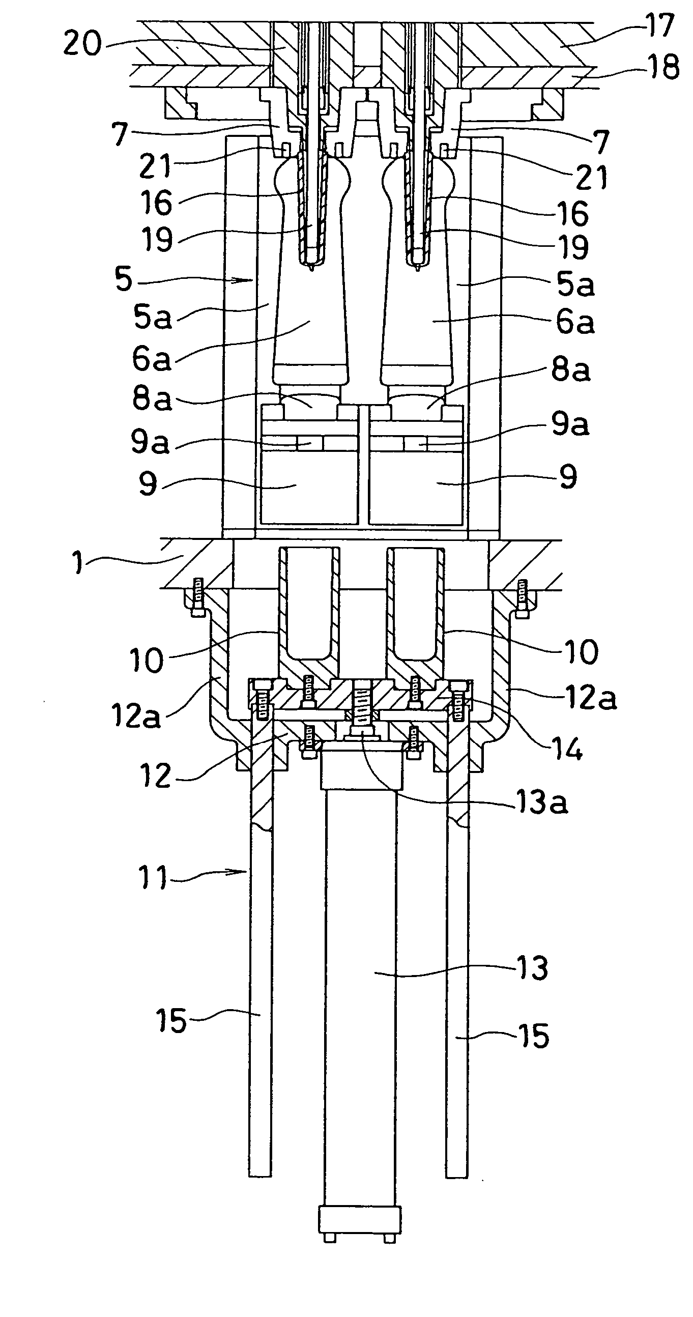
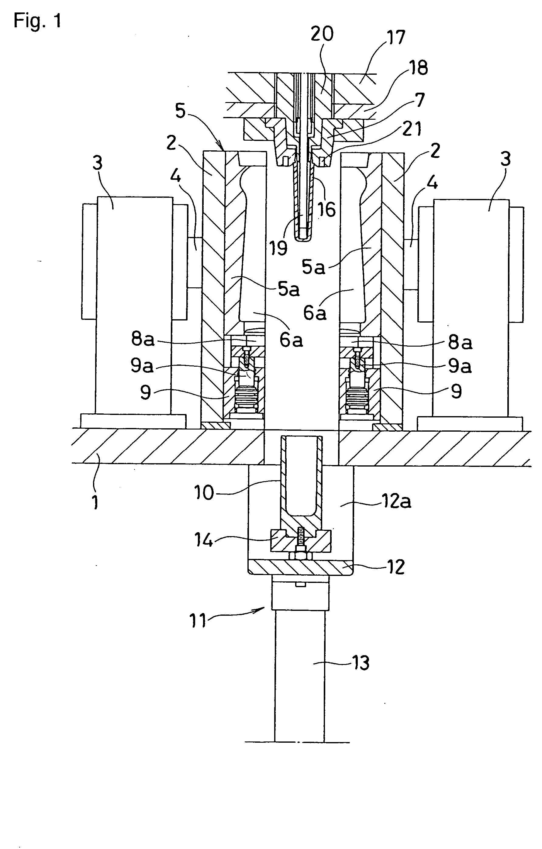
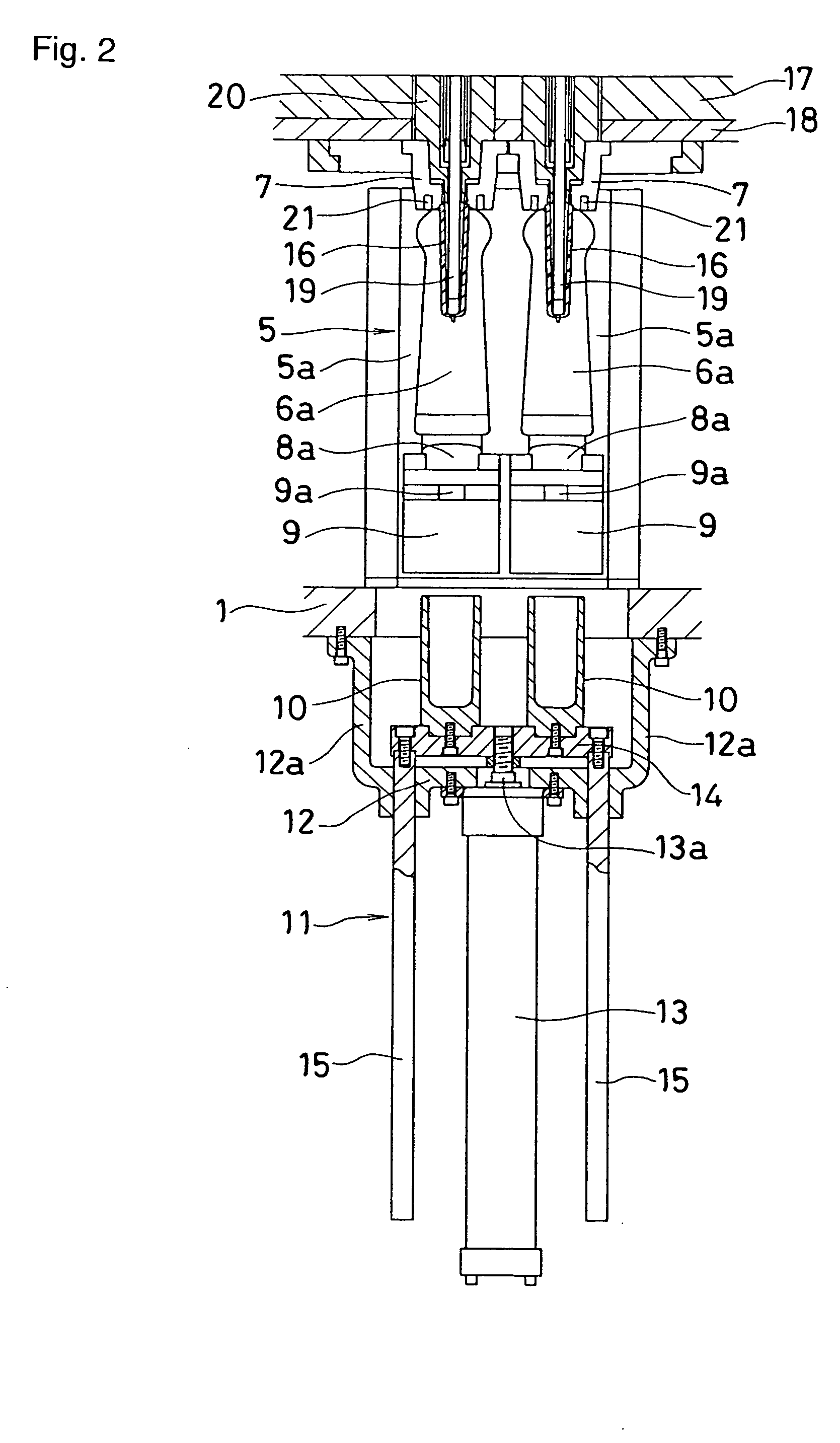
[0022] As shown in FIG. 1, a pair of platen 2, 2, is movable advance and retreat facing toward each other on the top of a bed 1. Piston rods 4, 4 of mold clamping devices 3, 3 placed on the top of the bed 1 are tied to the outer surface of platens 2, 2. On the inner surface of the platens 2, 2, a main blow mold 5 for molding an article (e.g. a bottle) is installed with being separated into split molds 5a, 5a, and concave cavity halves 6a, 6a, which form a cavity 6 (see FIG. 6) by closing the mold, are fixed on the parting surface of the split molds 5a, 5a.

[0023] Upper end of the cavity halves 6a, 6a connects to open halves, which fit to a neck mold 7. In the bottom of the cavity halves 6a, 6a, a bottom mold 8 (see FIG. 6) of main blow mold 5 is separated into split bottom molds 8a, 8a, and the split molds 8a, 8a are movable upward and downward via each of piston rods 9a, 9a of lifting cylinders 9, 9 which are hydraulically or pneumatically driven under the sprit bottom molds 8a, 8a...


PUM

PropertyMeasurementUnit
areaaaaaaaaaaa
lengthaaaaaaaaaa
sizeaaaaaaaaaa

Abstract

The present invention relates to a mold device having a combination of molds for stretch blow molding, comprising a main blow mold 5, installed on a pair of platens 2 by being separated into split molds 5a, a pre-blow mold 10, attached to a lifting device 11 under the area between the split molds 5a, and movable in and out from the area between the split mold 5a, a neck mold 7, which is fitted into the pre-blow mold 10 and main blow mold 5 respectively, a blow core 20, which is fitted in to the neck mold 7, and a stretch rod. The pre-blow mold 10 comprises a cylindrical member having an open end on the upper portion, which is fitted into the neck mold 7. A bottom mold 8 of the main blow mold 5 is installed in the bottom portion of the split mold 5a by being separated into split bottom molds 8a. Lifting cylinders 9 are placed under the both of the split bottom molds 8a in order to make the bottom mold 8 movable in and out from the bottom portion of a cavity.

Description

BACKGROUND OF THE INVENTION [0001] 1. Field of the Invention [0002] The present invention relates to a mold device having a combination of molds for stretch blow molding, comprising a main blow cavity, which is for molding a container such as a plastic bottle, and a pre-blow mold below, and pre-blow molding and main blow molding are operated at a same position. [0003] 2. Background Art [0004] A conventional art discloses a mold device having a combination of molds which uses a pair of split pre-blow molds, which can be opened and closed on a bed by a mold clamping device, and a pair of main blow molds, placed under the pre-blow molds which is movable upward and downward, and the main blow molds can be clamped with the pre-blow molds by the clamping device (reference patent: U.S. Pat. No. 5,635,226). [0005] The conventional device disclosed in U.S. Pat. No. 5,635,226 uses a pair of split molds for a pre-blow mold, so that a parting line is left on a preliminary article formed in pre-...

Claims


Application Information

Patent Timeline
Patent Type & Authority Applications(United States)
IPC IPC(8): B29C49/06B29C49/12B29C49/18B29C49/48B29C49/54B29C49/56B29C49/62
CPCB29C49/06B29C49/12B29C49/18B29C49/48B29C49/541B29L2031/7158B29C49/62B29C2049/4869B29C2049/4889B29C2049/4892B29L2031/7126B29C49/56B29C49/48185B29C2949/0715
Inventor FUJII, DAIGOMOCHIZUKI, TAKEKAZU
Owner A K TECH LAB INC
Why Eureka
Try Eureka